


")

Until all nodes in your vehicle perfectly, usually does not occur desire to think about what may come a time when the engine suddenly starts to give interruptions, "sneeze," and, finally, will refuse to work. But such the time sooner or later, unfortunately, comes, and often under the most favorable circumstances…
In determining the malfunction of the ignition system of the vehicle of great assistance can to provide the simplest indicators of sparking described in the article.
Faults that occur in the ignition system of the vehicle, characterized by the fact that to identify them alone can be difficult, both same - and faster and easier. It it is clear: it is impossible to be simultaneously and under the hood where you want to find the fault, and behind the wheel to start the engine. And four hands always better than two.
So many drivers tend to equip their cars for more indication devices that allow the driver when in the workplace, to obtain reliable information about the health of various units the ignition system. Typically, these indicators are very simple, to make them maybe even inexperienced Amateurs.
In Fig. 1,and shows a diagram of one embodiment of the health indicator contact breaker. When the contacts open, the current through the ignition coil does not leak indicator is de-energized. After shorting the voltage drop the primary winding is increased to the vehicle voltage, so HL1 led turns on.
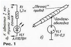
If the engine is running, the led flashes each time the contact closure breaker, and at low speed of the crankshaft separate flash distinguishable by eye. The desired brightness of led set selection resistor R1.
The indicator is performed by the circuit of Fig. 1,b, is designed to control high-voltage pulses in the "chart" wires of the motor. In this device a source of light flashes serves as a neon lamp HL1.
On the "chart" wire is wound bandage made of aluminum or copper foil (length winding - about 10 cm) and connects the flexible conductor-conclusion and attach a neon lamp. The brace serves as a capacitor plate of the capacitor through which part of the energy of the high-voltage pulse branches off the indicator.
If such an indicator should be provided for each spark plugs of the engine, placing the neon lights in the same order as the plug in the cylinders, you will get the opportunity to control all of the candles. Someone deems sufficient to have on Board one indicator connected to the bandage on the Central wire dispenser.
Health indicator contact breaker according to the scheme of Fig. 1,and is designed for work in the car with classic ignition system. If you have a machine installed contactless breaker with electronic ignition unit 36.3734, 3620.3734 or HIM-52 (foreign production), an indicator connected, as indicated in the diagram, to the primary winding of an ignition coil, will indicate the operation of the ignition unit, and not the breaker.
For controlling the operation of a contactless switch with Hall sensor is designed the indicator is collected by the circuit of Fig. 2. This high input device resistance, so it is almost not shunt the output circuit of the contactless sensor-breaker. The indicator input connected to the input of the electronic unit ignition (pin 6).
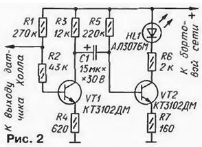
The indicator with neon lamp perform in the system with electronic ignition the same functions that previously described.
Some vehicles equipped with an electronic ignition system that does not contain the distributor. This system contains two non-contact sensor-interrupter, connected to the inputs (pins 19 and 8. 18 and 9, respectively) dual channel electronic controller electronics MS-02". The outputs of the channels of the controller (findings 4 and 3) are connected to the inputs of a two-channel ignition module 42.3734 (findings 6 and 5). The outputs of the channels of the block plug (pins 7 and 1) each loaded primary winding of the two ignition coils.
For controlling the operation of both channels of the controller in this system will require two the indicator according to the scheme in Fig. 2. connected to its outputs 4 and 3. To make it easier to distinguish the signals of one channel from the signals of the other, it is advisable apply in indicators LEDs red and green fluorescence. Connection indicators for the circuits shown in Fig. 1, has no peculiar features.
Some cars Volga car is equipped with a variety of electronic a different system than the previous one, because in it the functions of the controller and unit ignition combined in a single two-channel unit MS. For such a system, as practice has shown, is sufficient in the use of indicators by the schemes of Fig. 1. Two LEDs are connected in parallel the primary winding coils ignition, lights, neon lamps - each "chart" wire.
To protect the led (HL1, Fig. 1,a) from the accelerated degradation of the crystal due to pulse reverse voltage according recommend-consistently with led to include any silicon diode reverse voltage of At least 400
Author: A. Peltekian