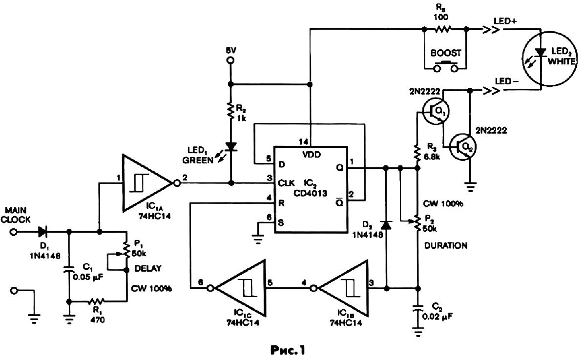
The device comprises a clock input MAIN CLOCK for supplying clock alarm and ultra-bright white led output. The delay and duration of the glow LEDs are governed by potentiometers P1 and P2. Used in the scheme is universal led 1 green LED light to indicate the presence of input signal, although, when the strobe operates at high frequencies, this led useless.
In Fig.1 shows a diagram of the led strobe.

(click to enlarge)
The input strobe pulse is supplied to the signal amplitude of 5 V and a duration approximately 30 μs from the fuel pump of the vehicle. The potentiometer P1 regulate the delay time of light in the range from 40 µs to 2 MS, and potentiometer P2 regulate the duration of the emission (or flash) led from 15 MS to 15ms.
Diode D1 and capacitor C1 form shaping circuit. Discharge rate capacitor C1 is controlled by ustanovki of the potentiometer P1. Inverting trigger Schmitt 1A IC monitors the voltage level on the capacitor C1. Once the low voltage reaches the trigger threshold 1C 1 AND, at its output appears high level, which is transmitted to the clock input of D-flip-flop IC2. The output Q established a high level. Open Darlington-Wai pair of transistors Q1 and Q2, the current flowing through bright white led, causing it to glow.
At this time, the capacitor C2 is charged, the charge rate is adjustable the potentiometer P2. When the capacitor voltage reaches the upper threshold inverting Schmitt trigger IC1, through the trigger 1C 1C reset D-flip-flop IC2 and its output Q is set high. Transistor pair closes and white light diode turns off. The circuit is now ready for another cycle.
Diode D2 provides a complete discharge of the capacitor C2.
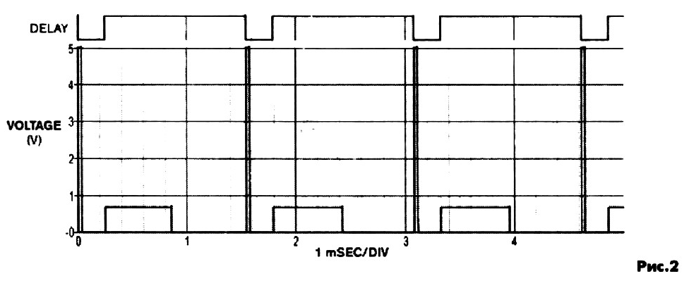
In Fig.2 shows diagrams of processes. The clock input voltages of 5 V with a frequency of 650 Hz. The upper curve of the graph shows the voltage on white Sveto-diode, the delay is about 250 μs (when P1 -10%) and duration of illumination approximately 600 μs (P2 - 75%). The lower curve shows the voltage at the output Q of D-flip-flop IC2.

(click to enlarge)
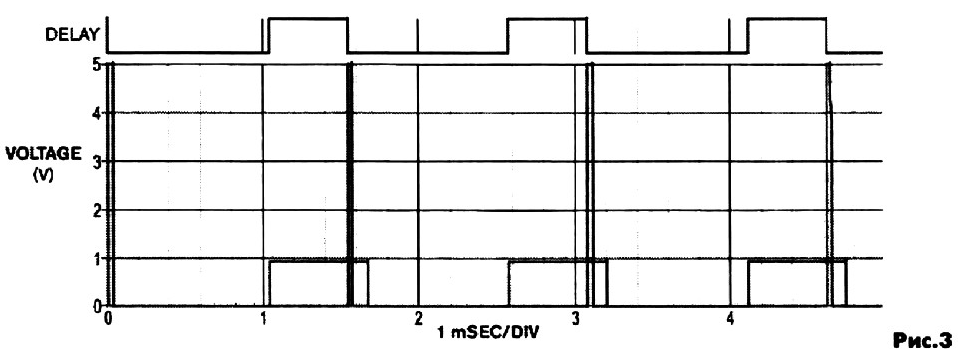
In Fig.3 shows a diagram with a different delay time for the same duration the illumination of the white light emitting diode (Fig.2). A new period of fuel atomization covers following the outbreak of the fuel mixture. Depending on injector nozzles can watch the end of one kalibrowannoj flash fuel mixture and the beginning of another.

(click to enlarge)
Strobe supplied with the switch for instant increase in intensity (with the resistance R3, the current through the led is approximately 40 mA). When you click BOOST through a pair of Darlington transistors 2N2222 current flows approximately 400 mA, i.e. continued use of the switch may cause the output down white led.
The time intervals can be calculated using the formula: T = 0.7 x R x C, where T is the time in seconds, R is the resistance in ohms and C is the capacitance in Farad.
Author: Paige M.


