


")

Know about the importance of setting optimum ignition of the combustible the mixture in the cylinders of a gasoline engine for maximum power, efficiency and proper temperature. The implementation of this work without instruments requires a certain amount of experience, takes a lot of time, and setting accuracy may be low.
A simple strobe allows you to quickly, accurately and with the minimum of hassle to set the angle ignition timing.
The emitter in the stroboscopic instrument factory manufacturing is instantaneous flash lamp providing light so bright flash that to set the ignition advance is possible even in the big ambient light. Unfortunately, the service life of flash lamps is small, and purchased new, correct type, is not easy.
With the advent of on the domestic market led with a luminous intensity of more than 2000 MCD (for comparison, LEDs series AL307-M with the same current value of this parameter 10… 16 MCD) is made possible their use in Amateur the stroboscopic devices. In the following design group of the nine LEDs KIPP-red glow. The prototype device was the device, published in the Bulgarian magazine "Radio, television, electronics", 1988, No. 8, p. 37.
The strobe signal based on the so-called stroboscopic effect. The essence it is as follows: if the light moving in the dark the very object short bright flash, it will visually appear as if motionless "frozen" in a position in which he caught a flash. Lighting, for example, the rotating wheel flares, with the following frequency equal to the frequency of its rotation can visually stop the wheel that is easy to notice on the status any label on it.
To install ignition start the engine to idle, and strobe lights special alignment markers. One of them is mobile - placed on the crankshaft (or flywheel or pulley generator) and the other on the motor housing. Flash will synchronize with moments tumors in the ignition the glow plug of the first cylinder, for which capacitive sensor strobe mounted on the high voltage wire.
In the light of the flares will be visible to both marks, and if they are exactly one against the other, the ignition timing is optimal, if the moving label offset, adjust the position of the interrupter-distributor until alignment marks. If the car has electronic octane-corrector, match labels achieve the appropriate knob. How to prepare the engine for this operation, you can read in the book "electric vehicles" (Handbook), edited by čížková Y. P. - M.: Transport. 1993.
Nourish the unit from the vehicle network. Diode VD1 (see scheme in Fig. 1) protects strobe from erroneous changes the polarity of the supply voltage.

Capacitive sensor device is an ordinary and an alligator clip, which is attached on the first high-voltage wire spark plugs of the engine. A voltage pulse with sensor, passing through the chain C1R1R2. is supplied to the clock input of flip-flop DD1.1, included a single vibrator.
Before the arrival of a single-shot pulse is in the initial state, the direct the trigger output is low, is inverted to be high. The capacitor C3 is charged (plus side inverted output), he is charged through the resistor R3.
The high level pulse triggers a single-shot, trigger switches and the capacitor begins to recharge through the same resistor R3 with direct access of the trigger. After about 15 MS, the capacitor is charged so that the trigger returns to the zero state at input R.
Thus, the single vibrator on a sequence of pulses capacitive sensor responds by generating a synchronous sequence of rectangular pulses high level of constant length is about 15 MS. The pulse duration determine the values of the circuit R3C3. Plus changes to this sequence. I start the second a single-shot, assembled according to the same scheme on the trigger DD1.2.
The pulse duration of the second single-shot up to 1.5 MS. At this time open the transistors VT1 - VT3, the components of the electronic switch, and through a group of LEDs HL1 - HL9 leak powerful current pulses - 0,7…0,8 A.
This current significantly exceeds the certified value of the maximum allowable pulsed direct mining (100 mA) that is set for the LEDs. However, since the pulse duration is small, and their duty cycle in normal mode not less than 15. overheating and failure of the LEDs is not marked. The brightness in the outbreaks, which provides a group of nine LEDs, is quite sufficient for the lights even during the day.
In order to verify the reliability of the instrument was held control elektrodragon svetoslava a dye at a current pulse of 1 A within the hour. All LEDs have withstood the test of time, overheating was found. Note that usually the time of use of the device is less than five minutes.
It was experimentally found that the duration of the flash must be within 0.5…0.8 MS. A shorter period increases the sensation of lack of brightness lighting labels, and in larger increases their "blur". Required the length is easy to pick up visually while working with strobe a trimming resistor R4. included in frameshadow chain R4C4 second a single vibrator.
The appointment of the first single vibrator to protect the LEDs from failure when random increase in the rotational speed of the crankshaft of the engine in the process the use of the stroboscope. Usually the installation of the ignition timing is carried out on the engine speed is close to idle. If the frequency of sparking will to increase, will decrease the duty cycle of outbreaks (since their duration fixed). When the frequency of sparking the release of heat from the LEDs may become excessively large, resulting in their failure.
The pulse duration of the first single vibrator is selected such that upon reaching the rotational speed of the crankshaft about 2000 min-1 duty factor of the output pulses this single vibrator closer to 1. With further increase of the input frequency the work of the trigger DD1 gets out of sync with it and the single vibrator begins to generate a random pulse duration and frequency. The averaged frequency actuation of the second single-shot mode in this mode significantly less dangerous limit.
Resistor R9 enhances the powerful closing of the transistor VT3 in the pauses between flashes. This transistor should be chosen with minimum the saturation voltage collector-emitter, then it will be much easier to provide the desired brightness of the flashes. If the brightness is insufficient, can to try to gather the output transistor switch according to the scheme shown in Fig. 2. In this case, by the way, will be limited to a safe level collector current of the transistors VT1 and VT2.
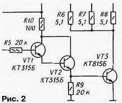
Resistors R6-R8 limits the current through the LEDs. The capacitor C2 suppresses the pulses of voltage in the supply circuit of the device that may cause undesired operation triggers. Resistor R5 limits the base current of the transistor VT1.
Chip CTM can be replaced by KTM. and based TM features of her body. Instead of the diode KDA suitable KDA. but the best the result will give diodes KDA, KDA-CDG, CDV, CDV, as they less forward voltage drop. Rigged resistor - SDR-196 or SP5-1. Capacitors - km-5, K73-9 or other; C1 must be able to withstand voltages up to 200 V.
Transistors KT315B can be replaced with any of a series KT3102. CT and CTA - any of the series KT815, CT.
The conductor from the sensor to the instrument should not be too long and definitely shielded, since the sensitivity of the device is very high. Switch SA1 - any motor or the switch TB2-1.
Strobe is the most convenient to collect in a plastic case from a pocket lamp. The LEDs are mounted on the disk with a thickness of 1 mm from the foil fiberglass adjacent to each other, secure the disc in place with the bulb of the lamp. The handle of the resistor R4 can be displayed on one of the sides of the chassis near the power switch SA1.
Correctly assembled, the device does not require the establishment. You only need to install optimal brightness and clarity of the observed labels resistor R4.
Author: P. Bialiatski, Berdsk Novosibirsk region.