


")

When adjusting the contact of the ignition system of the automobile engine it is necessary to measure the frequency of rotation of its crankshaft and the angle of the closed state of the contacts (KYC), characterizing the width of the gap between the contacts the breaker. Described in the journal of devices for this purpose [1-3] the measurement result bring to a scale pointer of the microammeter. Now many radio Amateurs appeared digital multimeters series M, M, M. Simple console to this multimeter will allow you to conveniently and with great precision to measure the frequency of rotation up to 2000 min-1 and the angle of the legislative Assembly in the range of 30 to 60 degrees.
Attachment easily connects to a multimeter. After activation the device is ready for use for its intended purpose.
Diagram of the console shown in Fig. 1.
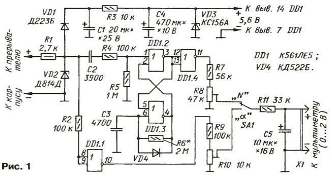
The device is assembled by only one digital the DD1 chip. The node of its food consists of decoupling diode VD1, charger the capacitor C1 and the voltage R3VD3 with a smoothing capacitor C4 connected to the voltage limiter R1VD2.
Powered console pulse voltage from the breaker contacts in the process of measurement of each option. As a result dostupnoi stabilization (R1VD2 and R3VD3) fluctuations of the supply voltage of the chip is not exceed 3 % when the duty cycle of the pulses from the circuit breaker from 4 to 1.25.
On the elements of DD1.2, DD1.3 assembled a single-shot generating pulses duration of about 8 MS. The pulse voltage limited by Zener diode VD2, arrives at the shaper short pulses C2R4R5 (resistor R4 is current limiting) that trigger a single-shot each time plus the differential input pulse sequence (i.e. when opened).
Formed by the same single vibrator voltage and duration of the pulses pass through the buffer element DD1.4, the voltage divider resistors R7, R8 and the mode switch SA1 shown in the diagram position "N" on integrated circuit R11C5. The capacitor C5 is allocated a constant voltage, proportional to the rotational speed of a crankshaft of the engine.
If the switch SA1 translate into lower on the diagram position ("a"), then the circuit R11C5 will be connected through a voltage divider R9R10 to the output of the inverter DD1.1. The input of the inverter through current limiting resistor R2 is connected to the same the Zener diode VD2. Each contact closure causes a low pulse level at the input of the inverter. Since the angle KYC is constant and does not depend on the frequency pulse, the voltage on the capacitor C5 will be in proportion to the angle KYC regardless of the speed of rotation of the crankshaft.
The voltage on the capacitor C5 is measured with a digital multimeter. connected to the connector X1.
Instead CLE in the console you can use the same functions on the chip from series C, K. The Zener diode VD2 can be used on any voltage in within 9… 12 V, a VD3 at the voltage 4.5…7 IN (KS147A, XA). Diodes VD1 and VD4 - any low-power silicon. The capacitor C5 is desirable to choose from minimal leakage current.
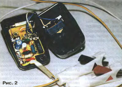
Details consoles placed on the Board size 40x35 mm. Conclusions skipped parts in the holes. The installation is made insulated wire. Board strengthened in plastic housing from the adapter active TV antenna. The mode switch SA1 - microtubles MT-1 is mounted on the lid of the housing. To the input of the consoles need to solder a flexible conductors with insulated the ' alligator clips on the ends.
View of the installation of the console shown in Fig. 2.
If there is a ham radio operator has a multimeter from the DT-890, which the distance between the centers of the sockets is approximately 19 mm, the pins available on the power supply case, it is necessary to connect the output of the console - they will go into nest "COM" (common) and "DCV" multimeter.
When the switch limits of the multimeter must be set to position "2000 mV".
To establish consoles her pins include in the socket of the multimeter, and the input from generator 3H serves sinusoidal voltage 12… 15 V with a frequency of 30 Hz or a sequence of rectangular pulses. The switch SA1 consoles set to "N", and a trimming resistor R8, they seek evidence "900" on the scale of a multimeter, which corresponds to 900 min-1.
By increasing the frequency of the generator to 50 Hz multimeter should show "1500" ±20 mV. If necessary, the position of the slider of the resistor R8 is correct. It is advisable check multimeter readings on other values of frequency: 20 Hz it must show "600", and 40 Hz "1200". Now the console is connected to breaker, four-cylinder engine and make sure it operates properly. The increase in voltage of 1 mV at the output of the console corresponds to an increase the rotational speed for 1 min-1.
After that, the switch SA1 consoles translate to "a". The input served rectangular pulses with a duty cycle 2 ("meander"), and trimming resistor R10, they seek evidence "45" on the scoreboard consoles (45 mV). When connect the input of the console to the breaker operating engine multimeter will show the angle of the legislative Assembly. An increase of one degree of angle KYC corresponds to an increase voltage of 1 mV.
The console can establish without a signal generator, feeding on its input AC voltage 15…25 V 50 Hz with a secondary winding of the step-down the mains transformer. In the "N" trimming resistor R8 consoles set on the scoreboard multimeter reading "1500". In the mode "a" engine trim resistor R10 is rotated until appears in the display multimeter readings "45".
The measurement error parameters with careful calibration of the set-top box exceed 3 %, which is sufficient for normal operation of the engine internal combustion engine.
It should be borne in mind that the setting time of the multimeter with the prefix some 3…4 because of the relatively slow charging of the capacitor C5 consoles and some of the inertia of the models of multimeters. By the way, instead of a multimeter you can use ordinary dial with avometra a high input impedance is not less than 50 ohms/V.
Literature
Author: I. Potechin, Fokino Bryansk region.