Octane-corrector described by V. Sydorchuk in [1], with subsequent modifications [2, 3] is still popular among hams-motorists due to the simplicity, exceptionally high reliability, excellent repeatability. Analyzing (as the author of the modifications) numerous mail magazine on this topic, I came to the conclusion that the main the difficulty lies in ensuring the normal operation octane-corrector with blocks plugs of different types.
Thus, in [2, 3], the design is intended to work with unit 3620.3734. To date, however, he discontinued and in connection with in different regions there are problems with its acquisition. Also the readers frequent questions on the connection octane-corrector to different industrial the ignition systems series "spark", "electronics", etc.

The purpose of this article is to help those who due to various reasons cannot to equip their cars octane-corrector V. Sydorchuk.
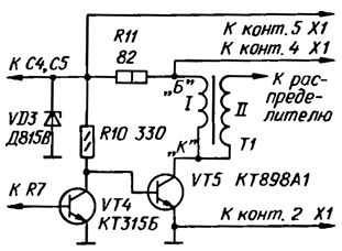
Tested octane-corrector with these modifications showed that described in [2, 3] the device can be successfully used as transistorized ignition system (i.e. available on the vehicle electronic unit ignition becomes unnecessary). For this purpose it is only necessary to Supplement the weekends the current amplifier transistors KT315B and CTA. In the illustration given scheme the output level of this unit to octane-corrector (Fig. 1 in [3]).
Octane-corrector collect on a printed circuit Board, a drawing of which is shown in Fig. 2 in [2] the ignition System to collect very convenient place in the building from motorcycle ignition module KAT-1A. The transistor VT4, resistor R10 is brazed to Board octane-corrector by printed conductors. The Zener diode VD3 set in a ready threaded hole M4 inside the housing, and the transistor VT5 - on the bottom, which is necessary to drill a hole and cut the thread MOH. The bottom surface of the housing in this place should be cleaned fine-grained emery paper. Before installing transistor its surface adjacent to the bottom, cover with heat-conductive paste KPT-8 or grease LITOL-24. Resistor R11 convenient to solder mounted to the mounting block at a time from the card installation permanently established octane-corrector.
Establishing octane-corrector in this embodiment does not differ from that described previously. The jumpers should be set under option B (VAZ-2108) for use with contact ignition system, the resistor R1 a 510 Ohm resistor, the input device to connect with clip switch, or under option A (VAZ-2106) applications with contactless ignition system of VAZ-2108, the resistor R1 the resistance of 2.7 ohms.
It should be noted that in the case of the use of the described system in cars groups VAZ-2108 and VAZ-2109 need to replace the ignition coil on 27.3705 BE. Some reduction in spark energy in this case, partially offset great time of accumulation of energy due to the increased duty cycle (2,57 3 against the VAZ-2106). On cars with contact ignition system and incremental the resistor in the primary circuit of the coil positive wire should be connected to the clip VK-B (threaded M4) coil.
Literature
Author: E. Adigamov, Tashkent, Uzbekistan


