


")

Decades of use on domestic and foreign cars units with electronic ignition collected under article Y. sverchkova [1] improvements suggested by G. Karasev [2], showed that these improvements together with good qualities (increase duration sparks, for example) result in failures in the sparking frequency of rotation of the crankshaft 3000 min-1 and more. Moreover, it was found that to completely eliminate these failures is extremely difficult, even if you follow the recommendations given in [3].
At the stage of establishment of the unit, it was found that the appearance of the clip "K" the ignition coil of the half-wave voltage after closing the diode VD5 (refer elements hereinafter correspond to the diagram in Fig. 1 in [2]) is very unstable. The characteristics of this wave is strongly dependent not only on the values of capacitor C2 and resistor R4, but also from the supply voltage, and to an even greater extent to the width spark gap.
Once installed on the car unit, adjusted and working at the stand without fail in the frequency interval of the pulse shaper 10…200 Hz with two periods of discharge of the capacitor C3 at a voltage of 14 V, spark the span of 7 mm, a disruption in the spark was evident at high rpm the crankshaft. Did not help any different combination of values capacity capacitor C2 (0.01 to 0,047 UF) and resistor R4 (300 to 1500 Ohms), or even a selection of SCR VS1-current control.
Crashing completely disappeared when the value of the resistor R4 over 1.5 ohms and capacitor C2 0.01 UF, i.e. when the single-cycle spark in accordance with the scheme block Y. sverchkova. Few years, the unit worked flawlessly with the remote circuit lengthening sparks C2R3R4VD6.
Analysis of the waveforms of the voltage clamp "To" ignition coil, obtained on installed in the car the ignition module with a chain lengthening sparks, the different frequency layers, leads to the conclusion that the cause of failures in the spark lies in the instability of the rate of increase of the half-wave the voltage on the capacitor C3, following the closing of the diode VD5.
Therefore, we have to admit that the method of increasing the duration of the spark discharge transtorno-capacitor unit by submitting to the control electrode the SCR re-opening of the pulse generated by the residual voltage on the storage capacitor, for practical use in the car unfit.
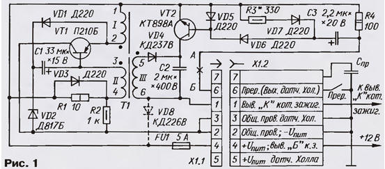
To implement the idea of increasing the duration of spark discharge in condenser ignition module [1] managed through the use instead the SCR powerful composite transistor CTA, specially designed for automotive ignition systems. Diagram of the upgraded unit is shown here on the Fig.1 (hereinafter denote elements correspond to the schema).
The control circuit of the discharge of the storage capacitor C2 is greatly simplified by compared to [2]. The time constant of the charging of the control capacitor C3 determine the values of the elements of C3 and R3 and the resistance of the diode VD7, and the discharge - C3 and R4, VD6 and resistance-emitter junction of transistor VT2.
The base current of transistor VT2 depends on the voltage across the capacitor C3, resistance diode VD6, resistor R4 and the voltage, which allows to establish a unit in bench conditions.
To establish connect the unit to the regulated power supply voltage up to 15 V and the load current 3…5 A and to the ignition coil, set of spark a 7 mm gap between the Central pin and clip "B". To pin 6 of connector X1.1 connect the output of generator of rectangular pulses with a duty cycle of 3 and load capacity not less than 0.5 A.
Very convenient for establishing take advantage of the octane-corrector [4] with auxiliary devices (it is only necessary to close the variable resistor R6 by Fig. 1 in [4]. In establishing the unit instead of the resistor R3 is connected AC nominal value of 2.2 kω, setting the engine to the maximum resistance. Include a power source for a voltage of 14 V and fed to the input of control pulses frequency from 10 Hz to 200 Hz, controlling the oscilloscope form voltage clamp "To" ignition coil - it should be it is shown in Fig. 2.
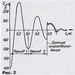
If the waveform is visible to only one period of oscillation of the voltage rotation engine variable resistor achieve the appearance of the second period with a mandatory visible clear boundary endings sparking. Then reduce the voltage power to 12 V and repeat the previous operation. This is followed by the verification operation at a frequency of 10…200 Hz at a voltage of 12…14 V. Measure the resistance of the entered part of the variable resistor and solder a DC resistor nearest denomination Usually the resistance R3 is in the range from 200 to 680 Ohms. In some cases, you may need to select the capacitor C3 in the range 1 …the 3.3 UF.
Reducing the time constant of charging of the capacitor C3 due to the resistor R3 is not impairs the security of block pulses from bounce breaker contacts, as the process of "bounce" is shorter than the time during which the base current of transistor VT2 reaches the value that is sufficient for its opening. When using the unit together with octane-corrector [4; 5] interference associated with the "bounce", suppressed more reliably.
The capacitance of the storage capacitor C2 of the ignition unit is increased to 2 µf with to increase the time of his discharge. In this case, the length of the first discharge period equal to 0.4 MS. In order that the capacitor has time to charge up to the occurrence of the next cycle of sparking, the inverter unit you need to force, increasing the thickness of a set of plates of the transformer T1 to 8 mm, and when the building block according to the method of Y. sverchkova selection of resistor R1 to achieve voltage 150… 160 In the capacitor C2 (the condenser need shall be shorted by a resistor of 1.5 kω power not less than 5 W). In this embodiment, the inverter continues in block securely to work for more than 6 years.
Diode VD5 according to the scheme of Fig. 1 in [2] from the block; it is the function of built-in protective diode of the transistor VT2 block. The capacitor C2 is MBGO, C3 - K53-1 or K53-4, K53-14, K53-18; apply aluminum capacitors due a large leakage current and low reliability is impossible. The transistor can KTA replace only with CTA, CTA or foreign BU931Z, BU931ZR BU931ZPF1, BU941ZPF1. Connector X1 consists of inserting the UNP-ZG-52-In-AE and sockets GST-ZG-52-R-AE.
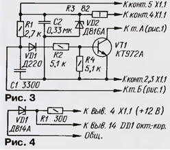
The described unit can be used in families cars VAZ-2108 and VAZ-2109, what will need to connect the unit to the left of connector X1.1 according to the scheme of Fig. 1 the matching node, collected by the circuit of Fig. 3 (cross marks the spot of the break circuit). If it is assumed, in conjunction with the ignition module to use octane-corrector [5], from the terminating node should be deleted resistors R1, R4 and capacitors C1, C2, to short circuit the resistor R2 and the diode VD1 and to connect the output octane-corrector [5] (the resistor R7) with the base of the transistor VT1 node. Zener diode The d816a need to replace DV, the positive lead of the power corrector connected to pin 5 of connector X1.1. Capacitors at node S1 - km-5 km-6, K10-7, K10-17), C2 - K73-9(K73-11).
When using the unit in vehicles of other types, having contact the breaker for the power supply of octane-corrector should install parametric a voltage regulator, Fig. 4.
The capacitor breaker off and the JWP solder it to pin 7 of the socket X1.2. Now for the transition to normal the ignition enough to insert into the socket X1.2 plug plug X1.3, which together contacts 1,6,7 (Fig. 1 not shown). Not withdraw the wire from the condenser breaker JWP to the socket X1.2 plug in X1.3, it is possible to provide the capacitor C4 K73-11 capacitance of 0.22 μf for a voltage of 400 V, connected between pins 1, 6, 7 and pin 2. In this case, the capacitor JWP just disassemble.
After this modernization provides uninterrupted block sparking with two periods of the total duration of the spark is not less than 0.8 MS the rotational speed of a crankshaft of the engine 30 to 6000 min-1 and the change voltage vehicle electrical system 12 to 14 V. the Engine began to work "softer" improved vehicle dynamics.
By reducing the voltage to 6 In block maintains uninterrupted sparking with one period in the range of frequency of rotation crankshaft, and doperide sparking continues until the frequency speed 1500 min-1 with decreasing on-Board voltage up to 8 V, which is significantly easier engine start.
Use block of the switching transistor instead of SCR also allows to increase the energy of the spark due to the almost complete discharge of the cumulative capacitor through the primary winding of the ignition coil, as in a condenser blocks the ignition pulse energy storage. This option was due to the fact that the block Y. sverchkova [1] is not afraid circuit the storage capacitor C2. The implementation of the specified quality is achieved the inclusion of diode VD8 parallel to the primary winding of the ignition coil (on the scheme unit shown by the dashed lines).
The process of discharging the storage capacitor to the ignition module with a continuous the accumulation of energy in the capacitor is somewhat unusual. When contacts breaker managing charging of the capacitor C3, and upon opening it is connected to the positive electrode through the diode VD6 to the base of the transistor VT2, and the net through a resistor R4 to the emitter. The transistor VT2 is opened and remains open as long as the current base - current discharge of the capacitor C3 is remains sufficient.
The storage capacitor C2 is connected through the transistor VT2 to a primary winding of ignition coil and is discharged during the first quarter of the period as well as in block [1]. When the voltage on the terminal "K" coil will pass through the zero value, the diode VD8 opens. The current in the circuit at this point reaches a maximum. Open diode VD8 shunt capacitor C2 connected through outdoor the transistor VT2 with the winding I of the coil, and therefore recharge capacitor not, it is discharged completely to the winding I of the ignition coil and all his energy is converted into its magnetic field.
Open diode VD8 supports the current in the circuit formed them and the winding I, and occurred during the first quarter of the period of the spark discharge. After all the stored energy of the coil is depleted, the spark stops. It should be noted that in this case, unlike the case of the oscillatory process discharge of the capacitor C2, the duration of discharge does not depend on transistor VT2 and is determined only by the capacitance of the capacitor C2 and characteristics of the ignition coil.
Thus, the transistor VT2 may be closed before or after the end of the spark discharge, reducing the accuracy of the adjustment block. Enough to fix it on the stand for the case of oscillatory process, and then just to solder the diode VD8. This property makes it universal. For example, if requires increased service life of spark plugs, the unit used in vibrational mode, the spark discharge duration of 0.8 MS, the steady running of the engine in any conditions. And when you want high energy spark (high demands the toxicity of exhaust gases), the unit makes use of the current process discharge by installing a diode VD8. Spark discharge during the test block with diode has the form of a cord of blue-Magenta colored transistor systems.
For upgrading already made blocks [2], no significant alterations not required. Transistor CTA and diode KDV freely placed on the existing the Board instead of SCR VS1 and chain elongation sparks C2R3R4VD6. The heat sink the transistor is not completely necessary, since the duration of flowing through it the current pulse is significantly smaller than in solid state systems.
After the upgrade significantly increases the pulse current consumed by the unit the ignition when the engine (when the engine is stopped, the current remains the same - 0,3…0,4 A). It is therefore advisable between pin 4 of connector X1 and General wire to connect oxide blocking capacitor 22 000 UF the voltage is not less than 25 V.
Of course, described the modernization of unit [1] does not exhaust the possibilities further increase of the duration and energy of spark discharge. So, for example, was tested method of connection of the primary winding of the ignition coil to the source power at the end of the cycle sparking. And although this unit turns more complex and, consequently, less reliable, in General, these indicators it superior to many others, described in the journal.
The schema fragment of the improved variants are depicted in the diagram Fig. 5 (the Converter remains unchanged).
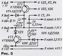
After the contact opening breaker the processes in the block in the first quarter of the period of détente the storage capacitor C2, similar to that described above (phase 1 in Fig. 6), however, in addition, charging of the capacitor C4 through resistors R4, R5, the emitter junction of transistor VT3. The charging current of the capacitor opens the transistor VT3 and keeps it in this state for a period of time determined the parameters of the elements of the charging circuit.
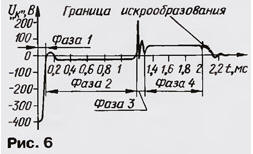
Once the voltage on the clamp "To" ignition coil will pass through the zero the value at the end of the first quarter period exceeds the forward voltage of the diode VD9, it will open and clamp "K" through the diode VD9 and the transistor VT3 is connected to a common wire. Through the primary winding of the ignition coil current flows from power source, multiplying the discharge current of the capacitor C2 and supporting arisen spark discharge (phase 2).
Further, the base current of transistor VT3 becomes so small that the transistor closed, disconnecting the primary winding of the ignition coil. Arising from this the surge voltage at the clamp K is about 200 V (phase 3 in figure) - it turns out sufficient to re-breakdown spark gap, so as to this point the spark actually has not yet been finished and re-strike occurs in the prepared environment. Further, the discharge flows in transistor system (phase 4 in Fig. 6).
After the circuit breaker contacts, the capacitor C4 is quickly discharged through the resistor R5 and the diode VD10, getting ready for the next cycle of sparking.
The total duration of spark discharge in an improved block is equal to 2 MS and remains almost constant in the frequency interval of the pulse shaper from 10 Hz to 200 Hz at a voltage of 14 V.
The establishment of this unit is not difficult. First establish it with disabled by transistor VT3 as described above. Then connect the transistor VT3, instead of a constant of the resistor R5 is connected variable the resistance of 2.2 ohms and set the engine in the highest position resistance.
Include the power supply and set the voltage of 14 V. the Rotation of the engine the variable resistor are making to the shape of the voltage clamp "K" coil ignition corresponded shown in Fig. 6 in the frequency interval shaper pulses from 10 to 200 Hz, then instead of the variable resistor soldered constant corresponding resistance (usually from 430 to 1000 Ohms).
Tests were conducted with the ignition coil B for contact systems GAZ-24 in a closed series resistor. Circuit this resistor there is no fear - coil do not overheat, as the time of spark discharge, generated by block in each cycle, less time spent coils inflow when the closed breaker contacts in a conventional ignition system. In the case of other ignition coils optimum capacitance of the capacitors C3 and C4 you may need to clarify experimentally.
The efficiency of the node on the transistor VT3 appreciate, after disabling the establishment of the capacitor C4. Set the frequency of sparking 200 Hz and relate the output capacitor C4 in place of his off - the sound of spark discharge must change, and cord sparks to get a bit thicker, with the formation of around him, the bright cloud of ionized gas as spark discharge, forming a transistor systems. The risk of damage to the transistor VT3 when this.
The transistor VT3 must be installed on the unit body, brushing the adjacent surface paste KPT-8 or grease Litol-24. If instead CTA (or BU931ZPF1) used a different transistor, it is necessary to enclose insulating mica strip.
A drawing of the circuit Board unit according to the scheme of Fig. 1 is represented in Fig. 7.
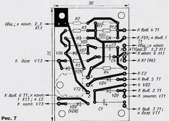
Fee designed to ease the Assembly of any described the article version of the ignition unit. The resistor R1 for the convenience of establishing composed of two - R1.1 and R1.2. Instead of diodes D you can use KDE, CDV, CDB; instead DW suitable KDE-CDV, CDV, CDG, KDV-CDD, CDG, and instead KDV (VD8) - CDG, CDG, CDG. For octane-corrector necessary to provide a separate cost.
The transformer T1 is assembled on the yoke Sh. The plates are assembled back to back, into the gap put a strip of fiberglass thickness of 0.2 mm. Winding I contains 50 turns the PEV-2 0,55 (thicker - up to 0.8), winding II - 70 turns of wire sew-2 with a diameter of from 0.25 to 0.35 mm, winding III - 420-450 turns of wire sew-2 diameter of 0.14 to 0.25 mm.
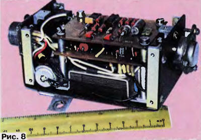
Photo of one embodiment of the ignition unit (without cover) is shown in Fig. 8.
Literature
Author: E. Adigamov, Tashkent, Uzbekistan