Motorists who installed it on your car's electronic ignition system probably already appreciated its benefits. Contact the breaker continues to trouble. Erosion, oxidation, contamination of the contact force motorist periodically to maintain them in working condition. To get rid of these worries can, if complemented with an electronic ignition system a pulse shaper with a proximity sensor.
There are several types of sensors that can operate in a contactless ignition systems - photovoltaic, galvanomagnetic, parametric. To parametric include those sensors, the basis of which lies the transformation changes the measured value in the edit parameters - capacitance, inductance, resistance, magnetic resistance. The most affordable for manufacturers in Amateur conditions parametric electromagnetic transducer. His work is based on the property of the magnetic circuit of the coil in which an alternating electric current to change its magnetic resistance when introduced into the magnetic gap of a ferromagnetic material with a low specific magnetic resistance.
In the literature, several described parametric sensors for contactless ignition system, for example [1,2,3]. In these constructions, the sensor coil wound on W-obrana ferrite magnetic core, a part of the blocking oscillator. This decision many disadvantages - complexity of manufacturing in Amateur conditions of the magnetic sensor is too small gap between the magnetic circuit and the switching disk, a large current consumption.
Below is described the design of non-contact breaker with electromagnetic sensor that is free from these drawbacks. Non-contact breaker can work together with all modifications of electronic ignition systems of industrial manufacturing ("electronics", "spark", "GROOVE"), as well as Amateur constructions described in [1.4,5].
These electronic ignition system is designed for the connection of the contact breaker, so the input node they are constructed in such a way as to ensure that the current through the closed contacts of the interrupter 70...180 mA. Such a significant current is selected to reduce the sensitivity of the system to the state of the breaker contacts . Mandatory electronic ignition system is a node of suppressing contact bounce. The use of non-contact breaker allows to exclude from the system node suppress contact bounce to choose much less current input node and thus make it more reliable and economical. In this article it is impossible to give recommendations on the modernization of the ready ignition systems, as there are many schematics of both commercial and Amateur.
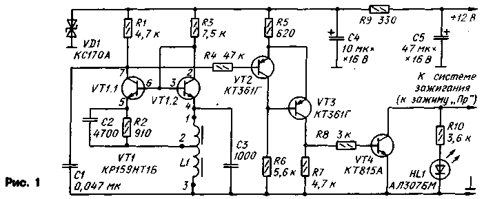
A schematic diagram of a contactless switch shown in Fig.1. The sensor is a coil 11, which together with capacitor NW part of the generator, transistors VT1.1, VT1.2 micro-VT1. When entering the tooth of the disk in the magnetic gap of the coil is the breakdown of oscillation of the generator, so that the energy of the electromagnetic field of the coil is consumed for the formation of eddy currents in the tooth.

At this point, the collector current of the transistor VT1.1 is reduced, causing an increase in voltage at the collector. Schmitt trigger, transistors VT2, VT3, generates a signal with a steep front and a recession. The transistor VT4 operates in the switching mode.
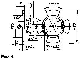
The occurrence of the tooth of the switching disk in the gap of the sensor corresponds to the moment of the circuit breaker contacts. The equivalent angle of the closed state of the contacts is mainly determined by the angular width of the teeth of the disk; this angle is chosen equal to 50°. A small error in the determination of the angle of the closed state of the contacts due to the hysteresis of the Schmitt trigger.
Temperature stabilization of the generator is provided with a negative feedback DC current through the resistor R2 in the circuit of the emitter of the transistor VT1.1, compensation diode (diode turning on of the transistor VT1.2) and the use of a matched pair of transistors placed on a single chip. The current through the emitter junction of transistor VT1.2 you have selected is small, about 1.5 mA. Thanks to these measures, the stability of the regime of the generator is maintained in the temperature range -48...+90°C.

The supply voltage generator and a Schmitt trigger is fixed by the Zener diode VD1, which eliminates the dependence of the moment of ignition voltage from the vehicle network. HL1 led is used to set the ignition timing and visual verification of operation of a circuit breaker.
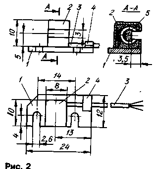
Coil L1 is wound on an annular magnetic core size 1(HH ferrite 2000NM. In the magnetic core propylene through slot width of 3 mm, and the winding is placed on the side opposite the groove. The winding consists of 37+50 turns of wire sew-2 0,12. Width of the winding - 3,5...4 mm Magnetic circuit in place of the winding wrap one layer of varnished cloth or cover with several layers of varnish.
To the winding soldered conclusions length 200 mm of wire MGTF, insulate the joint and insert the coil into the shielding box with a slit in the front. The position of the yoke 5 in box 2 and placing it on the mounting flange is illustrated in figure 1.2. The box can be made from sheet copper or brass (not steel) with a thickness of 0.2...0.4 mm., the Magnetic circuit is fixed relative to the slot, inserting the liner is made of porous rubber, wrapped with plastic wrap, then fill the box with epoxy.
After solidification of the resin box is brazed to the flange 1, is made of foil fiberglass, brass or steel. Wiring conclusions 3 is fixed on the flange yoke 4, fixed by soldering.
In the electronic node is applied to the resistors MLT, capacitors C1-7 (S1 - Sz), K53-14 (C4, C5). Transistor Assembly CRN replace the individual transistors is extremely undesirable, as it will deteriorate the stability of the oscillator, particularly in the region of negative temperature values.
All the details of the driver, in addition to the coil L1, placed on a circuit Board from a foiled fiberglass thickness of 1 mm. The drawing Board is presented in Fig.3. Fee established in durable, tight-fitting box should be mounted as close as possible to the interrupter-distributor of the car.
The establishment of the shaper is reduced to the selection of the resistor R3. By connecting a voltmeter to the collector of the transistor VT1.1, choose this resistor with a minimum of voltmeter - the voltage should be 2...3 V. Then introduced into the slot gauge steel plate. The voltmeter reading should increase to 6...to 6.5 V.
Design of gear drive is designed for installation on a four-cylinder engine shown in Fig.4. The disc can be made of any low-carbon mild steel. It is fixed with a grub screws on the Cam breaker.


Installation of the coil in the circuit breaker has features depending on the type of breaker-ignition distributor. Below we consider a variant of its installation in the interrupter-distributor R-118 car "Moskvich-412". You have to remove the distributor, "runner" and a vacuum regulator. Then, by removing the screws that secure the stationary plate to the bottom of the breaker, remove it, disconnect the movable and the stationary plate. Remove from the movable plate contacts in collecting and cut a brass axle pin rack flush with the plate. To drill the aluminum rivet fastening of a rack of wool felt lubrication of the Cam and remove the wool felt.
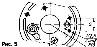
On the movable plate to be drilled in accordance with Fig.5 two drill holes with a diameter of 2.1 mm and cut thread M2,5 for mounting the coil sensor. To restore the connection plates and secured to the movable plate with the two screws M2,5 flange with sensor. Set the plate in place, put a gear drive for the Cam to adjust the position of his teeth in the groove of the sensor so that the gaps at the top and bottom were the same and lock the disc two locking screws M2.
After all electrical connections turn on the ignition and turning the starter crank the crankshaft of the engine, to ensure the actuation of the contactless switch on the ignition and extinction of the led. You can then start the installation of the moment of ignition. The methodology of this process is well described in the operating instructions of the vehicle. The ignition timing corresponds to the inclusion of the led.
Cost driver can be embedded in a casing of an electronic ignition system.
Literature
1. V. Stakhanov. Transistorized ignition system. Radio, 1991. 1989, pp. 26-29.
2. A. H. Sinelnikov. Electronic devices for cars. - M.: Energoatomizdat, 1986.
3. V. Gorkin, A. Fedorov. Contactless ignition system. - Sat. "To help the radio Amateur". vol.73. - M.: DOSAAF, 1981.
4. Y. Crickets. Stable multi-strike ignition module. Radio, 1982, No. 5, pp. 27-30.
5. G. Karasev. Stable unit electronic ignition. Radio, 1988, No. 9, pp. 17,18.
Author: A. Kolotov, Berdsk; Publication: N. Bolshakov, rf.atnn.ru


