


")

In certain circumstances the selection circuit design blocks for ignition motorcycle engines today is very narrow. This, of course, creates a large difficulties motivedecay-experimenters in the field of electronics introduction to two - and three-wheeled vehicles with two-stroke engine. In the article describes a simple thyristor ignition unit for two-cylinder engines motorcycles with two ignition coils. Under the scheme, he does not claim to a crucial difference, but impresses with its perfect design, does not require scarce parts, unpretentious in operation. On his motorcycle with this unit the author spent more than a dozen seasons.
Schematic diagram of the ignition unit for a two-cylinder motorcycle the engine is equipped with two ignition coils (example - motorcycle IZH-Jupiter"). it is shown in Fig. 1. The traditional block structure. Two transistors VT1, VT2 and the transformer T1 assembled on-Board voltage Converter power supply increased (310…320), feeding the dual ignition driver the pulses. The channels according to the scheme are identical and loaded each of its the ignition coil (12,13).
The frequency of oscillation of preobrazovaniya -3000…3500 Hz. When a vehicle voltage power 6 In block consumes at idle (ignition on, engine not running) current of 0.4…0.5 A, at the maximum rotational speed of the crankshaft is not more than 3 A.
Next, we will talk about the work only upper circuit channel. In the lower proceed the same processes, but they are shifted in phase by. 180 deg.
High DC voltage output from the rectifier bridge VD1-VD4 charges through the diode VD5 and the primary winding of the ignition coil 12 cumulative the capacitor C3. When the contacts of SF1 circuit breaker are closed, through a resistor R3 charged from the electrical system starting capacitor C5. At the time of opening this the capacitor discharges through the resistor R9. R10. diode VD7 and managing the transition the SCR VS1.
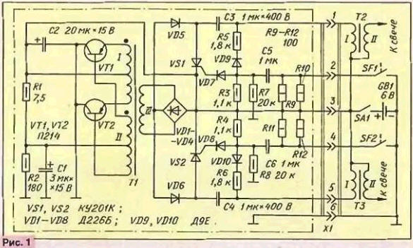
Opened the SCR discharges the storage capacitor C3 to the primary winding of the ignition coil. Impulse discharge current generates in the secondary winding coil T2 of the high-voltage impulse.
Chain VD9R5 reduces the time it takes to discharge the storage capacitor C3. which increases host performance. The resistor R7 creates a delay time charging pad capacitor C5. what prevents a node from false positives when you bounce breaker contacts SF1 at the time of their closure.
Decoupling diodes VD5 and VD6 at the time of sparking. alternately closing, provide discharge only one of the two storage capacitors. So. when opened SCR VS1, closed diode VD6 and Vice versa.
At the time of sparking the Converter output voltage is shorted low resistance open SCR VS1 and diode VD5. therefore, fluctuations frustrated, he ceases to draw current from the electrical system, and the output of the bridge VD1-VD4 voltage is reduced to zero. Upon completion of the cumulative discharge capacitor C3 SCR VS1 is closed, the generator Converter again starts and begins a new cycle of charging the storage capacitor.
To install the unit on motorcycles with 12 volt vehicle's electrical system must only to adjust some part types of parts and the number of turns of the transformer, the pattern remains unchanged. So. resistor R1 should have a resistance of 30 Ohms. R2 - 360 Ohms. R3 and R4 is 1.2 kω, R5 and R6 is 1.2 ohms. R9-R12 -200 Ohms. Diodes DE it is necessary to replace A capacitor C1, the other with a capacity of 5 UF voltage 25 Q. and C2 -20 ICF - for a voltage of 25 V.
Consumed by the unit current at 12 V, the power is about half that when 6 volt, other features remain basically the same.
The transformer is wound on three stacked annular magnetic cores CHH ferrite MNM-2. The number of turns of the windings and mark the wires indicated in table. The first coil winding 111, then II and I. the Turns of each coil have evenly around the ring. The interrow and winding insulation is made with a tape made of varnished cloth. in a single layer, and two or three respectively. This should keep in mind that the stock seats in the lumen of the magnetic circuit is limited.
The block is connected to other circuits of the ignition system through a six-slot X1. Use any connector, easy to use, and can withstand operating current through the contacts.
The constructive design of the unit is arbitrary. For transistors fairly common heat sink area of 40…50 cm2, attach them without spacers. Triacs establish through the mica strip on the heat sink area of 8… 12 cm2. The heat sink may be a metal casing of the unit.
Accurately mounted from the healthy parts of the unit begins to work immediately and the establishment is not required. The capacitance of the capacitor C2 is not critical, but from the capacity the capacitor C1 depends on the frequency voltage Converter.
Together with the ignition unit can operate any motorcycle coil ignition 6 and 12 V. as well as car, designed for classic variant of ignition.
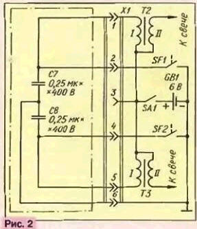
Connector X1 allows rapid transition to electronic the ignition on a classic. It is enough in the socket part of the connector insert a "capacitor" cap circuit is shown in Fig. 2.
In conclusion - a few tips and warnings. First, do not forget remove capacitors, shunt the contacts of the interrupters. Note mount transformer - it should be made so. to the mounting the items did not form a closed loop around the magnetic core.
No need to increase the output voltage in excess of 320 V. This only increase the leakage current through the triacs and adversely affect the the reliability of the unit.
The engine of the motorcycle IZH-Jupiter" in the classical ignition contacts breaker opens when the corresponding piston is at 2.2 mm from "top dead center". For e block, this value should reduce to 1.8 mm.
During the years of operation of a motorcycle with electronic ignition unit I I had to go with the battery, with battery and galvanic elements, and even without a power source, a starting motor with overclocking, I don't remember case to the unit caused the criticism.
Author: V. Gusev, Golitsino, Moscow region.