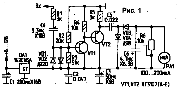
In many motorcycle, scooter, snowmobile and other motorcycles missing such an important instrument as a tachometer. Offer a simple and reliable tachometer. It is designed to work with single-cylinder two-stroke internal combustion engine with a contact or contactless ignition system and allows to measure the engine speed up to 10000 rpm diagram of the tachometer shown in Fig. 1.
In the initial state, the transistor VT1 is closed and VT2 open. At this time the left (the scheme) of the plates of the capacitor 5 is connected through a low resistance open transistor VT2 bus +5 V. the Current at this time through the microammeter RA1. During the first negative half cycle of the alternating voltage fed to the input of the tachometer, the transistor VT1 is opened, and VT2 is closed. At this time quickly C5 is charged through microammeter RA1, VD3 and R5.

During the positive half-cycle of the input voltage VT1 is closed, and VT2 is opened. Now C5 is discharged through a low resistance open VT2 and VD4. During the next negative half cycle, the process is repeated.
A trimming resistor R6 sets the upper limit frequency of the measured signal. The value of C5 is selected depending on the engine type. The higher the engine speed, the shorter should be the capacitance of the capacitor C5. Properly collected scheme does not require adjustment. You should only trimming resistor R6 to set the maximum reading from the tachometer sensor by opening the throttle valve of the engine to the end.
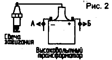
Wiring diagram of the tachometer to the electrical system of the motorcycle shown in Fig.2.

If the ignition pin, the input of the tachometer is connected to point A. For contactless ignition - to point B.
Author: S. Owl, Brest region, Kobrin district, p. Orekhovsky; Publication: N. Bolshakov, rf.atnn.ru


