Unfortunately, in many domestic and imported cars no a very important instrument - tachometer.
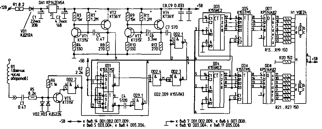
Offer a simple but well working on my car "Ford Escort" electronic tachometer. Based on the scheme published in [1]. The device has a two-digit digital indicator shows the number of thousands .hundred rpm. Powered tachometer from the vehicle network and consumes 0.45 A. Schematic diagram of the device shown in the figure.
The tachometer consists of a management node on the IC DD1 elements and DD2.1, DD2.3, DD2.4; two generators transistors VT1...VT4; the input of the pulse shaper is a Schmitt trigger VT5, DD2.2; counter pulses on the IC DD3, DD4; intermediate memory on the IC DD5, DD6; decoder on the IC DD7, DD8 and indicator H1.
The work of the management node is described in detail in [1]. The multivibrator on VT1, VT2 sets the measurement time, and the multivibrator at VT3, VT4 determines the duty cycle of the device. The input shaper and counter collected according to the standard scheme and features have not, therefore, immediately start to work. In the scheme of the tachometer introduced intermediate memory triggers to eliminate the flicker of digits of the indicator during the account. Synchronized triggers CTM signal output 8 DD1 passing through the capacitor C4 and DD9.1 to obtain the desired duration and phase. The cycle time is set by selection of the resistor R11, and the time of measurement, the selection of the resistor R7.
For a typical automotive four-stroke four-cylinder engine used an inductive sensor. It is a 50...70 turns of wire PEL 1.0, wound turn to turn on the high voltage wire connecting the distributor to the ignition coil.
One end of the coil of the sensor must be isolated, and the second is to connect to the input of the tachometer.

(click to enlarge)
The frequency of ignition pulses and the number of revolutions of the engine are connected by a formula: f=2n/60 where f is the frequency of the ignition pulses; n is the number of revolutions per minute of the motor shaft.
So, the value of the number of revolutions of 3000 corresponds to a pulse frequency of 100 Hz. But as the tachometer indicator should show at this time 3.0, the counter should take only 30 pulses of 100 per second. Therefore, the measurement in this case is set to 0.3 s. the cycle Time should be 10...20 times more (3...6).
Design and details. Two-digit digital indicator Bulgarian production VQE24 can be replaced by two domestic - ALSB or ALSB. If you replace the decoders CRED on KID, can be excluded from the scheme resistors R13...R19, R21 R27...and to apply the indicators ALSO with common cathode. All products series 155 can be replaced by the corresponding series 133, 555, 1533. Transistors KT315 can be replaced by CT 12, and KT361 on CT. Diodes VD2, VD3 - - any silicon: CD, KD521, CD. Capacitors C1, C2, C6 - K53-1, K53-14; C3, C5 - K73-17; other - KM5, KM. IC voltage regulator DA1-type CREA, can be replaced by CREW.
All the details of the electronic tachometer, except R1 and digital display placed on a bilateral PCB size h mm Board is placed in polystyrene housing size him. DA1 is set on a small finned heat sink. The resistor R1 decreases to about 5 V, which greatly facilitates the thermal regime of the stabilizer. If all parts are working properly, the device immediately begins to work. The establishment is as follows: the base VT5 the signal frequency of 100 Hz, and the selection of R7 set the indicator 3.0, which corresponds to 3000 rpm.
In conclusion, I note that under this scheme, my friends collected some tachometers, differing only in a constructive way, and they all have several years of excellent work on different cars.
Literature
- Shirokov B. Digital tachometer//Radio. - 1983. - N9. - P. 28-29.
- Biryukov, S. Digital devices-integrated circuits. - M.: Radio and communication, 1984.
Author: V. Kravchuk, Brest; Publication: N. Bolshakov, rf.atnn.ru


