


")

The driver is sometimes interesting to know how the number of revolutions develops the motor car. To determine this by using a simple transistor tachometer (Fig. 1), a measuring device which, graduated in the numbers of revolutions, conveniently positioned close to the steering system.
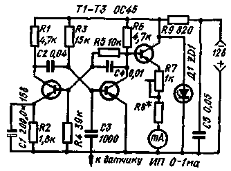
Fig. 1
The basis of the tachometer is driven multivibrator transistors T1. T2. He gives a narrow rectangular pulses with a duration of about 0.5 us, with a constant amplitude. The constancy of the amplitude of the output pulses is achieved by stabilization of the supply multivibrator voltage using a Zener diode D1.
The transistor TK is enabled by an emitter follower, is used for matching the output impedance of the generator with internal resistance measurement head IE. The indicator gives indications for admission to the base of transistor TK pulses from the multivibrator. Since their amplitude and duration is constant, then the readings are directly proportional to the repetition rate of these pulses. What they're, the greater the reading device.
Control the multivibrator pulses are fed to the capacitor C3 and the base of transistor T2. They are obtained with a capacitive sensor, in the form of a few turns (5-10) wire PELSHO 0,31 wound on a common wire, the power supply to the distributor (Fig. 2). So the sensor is not moved along the wire, its beginning and end of the reinforcing adhesive vinyl chloride tape.
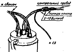
Fig. 2
The calibration of the device produced according to the scheme of Fig. 3 by means of a generator of rectangular pulses. The output voltage of the generator set about two volts. Operation tachometer he receives 4, 6 or 8 pulses (ignition system) in one revolution of the motor shaft, depending on the number of cylinders. Thus, the number of turns equal to the number of received pulses, divided by the number of cylinders. For example, if the frequency of the pulses from the 4-cylinder motor is 10,000 per minute, the number of turns is 10 000 : 4=2 500 Rev/min.
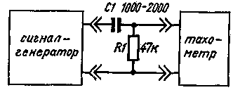
Fig. 3
The readings may be erratic or incorrect, if the rpm sensor serves pulses with excessively large amplitude. In this case, it is necessary to reduce the number of turns of the sensor.
If it is not possible to use the measuring signal generator, with sufficient accuracy for practice, you can calibrate the tachometer using a conventional ohmmeter. In this case, you need to find the total resistance of the resistors R7 and R8 according to the table.
Maximum rpm, rpm
4-cylinder
6 cylinder
R7+R8, Ohm
R7+B8, Ohm
5 000
8 000
10 000
180
520
800
500
1200
1500
The design of the device can be any. Easiest mounting plate and carrying the main elements that attach to switch the device back to its output terminals.
In the tachometer, you can use any low-frequency, low-power transistors, for example, MP and Zener D or D.
Literature
Publication: N. Bolshakov, rf.atnn.ru