


")

In the magazine "Radio", 1983, No. 9 at p. 28 in the article by B. Shirokov described digital tachometer used to measure the rotational speed of the crankshaft of the vehicle engine. A relatively simple attachment to this vehicle tachometer, described below, can be used simultaneously and to monitor compliance with speed limits of the vehicle.
Depending on the requirements of road signs the driver presses one of the buttons select the maximum speed displayed on the front panel. Once selected speed value is exceeded, on the panel will turn on flashing light of red color and an intermittent beep. The alarm continues until the speed will be reduced to an acceptable value or until another button is pressed, corresponding to a higher speed limit. Thus, the driver is relieved from having to constantly monitor the speedometer and can pay more attention to the road.
The device has five buttons corresponding to the limits of 40, 50, 60, 70 and 90 km/h Alarm is activated when you exceed the speed limit by 0.5…2.3 km/h. Alarm only works when the car is on a straight transfer. Consumed from the electrical system current does not exceed, 25…30 mA.
Improvement of the tachometer is adding a decoder, trigger the alarm and the alarm device.
The decoder (see diagram) assembled on a chip DD1, and DD2 is designed for decoding the numbers of 1.6; 2.4 GHz; 2,8; 3,5 corresponding to the values of speed of movement of 40.8; 51,5; 61,3; and 71,5 to 89.8 km/h. When the output of counters D2, D5 tachometer binary-decimal code. matching any of these numbers, the corresponding output of one of the logic elements DD1.1, DD1.2,DD2.1 - DD2.3 annunciator will appear a voltage with a logic 0 level. For example, the appearance of a binary-decimal code number to 2.4 at the output of the tachometer counters to both inputs of a logic gate DD2.2 detector signals to logic 1 and its output signal to appear 0, through which the contacts button SB3.1 (of course, if the button is pressed) is input to trigger the alarm. The trigger is assembled elements DD3.1, DD3.2, is established in one state. From the output of the element DD3.2 signal 1 is input to the element DD3.3 and will allow the alarm can be collected on elements DD2.4. DD3.3, DD3.4 and the transistor VT1.
On upper circuit input (pin 12) of the element DD2.4 multivibrator with tachometer received impulses that form an intermittent sound and flashing light indication. The audio signal generated by the generator DD2.4. DD3.3, DD3.4, strengthen the transistor VT1, the load of which is the dynamic head BA1. For light indication of Overspeed in the collector circuit of the transistor VT1 is connected a line of LEDs VD1-VD5, switch contacts SB1.2-SB5.2. depending on the pressed button will be included one or the other led.
Trigger the alarm periodically switches and the initial state of the signal produced by the second multivibrator tachometer, and then back again in one state, if the vehicle speed remains above valid or remains in the zero state, if the speed is reduced.
In the indicator switch used P2K radio. Limit switch SA1 similar to those used in the car to turn on the lights in the cabin when the door is opened, is placed under a protective cover at the base of the gear lever. This switch is set so that its contact opens when you enable direct transmission, while all other positions of the lever remained closed.
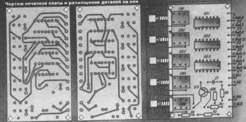
All elements, except for LEDs and dynamic heads placed on a bilateral PCB size H mm foil fiberglass 1.5 mm thick (see Fig.2). Button switches SB1-SB5 displayed on the front panel. Above the buttons set the LEDs VD1-VD5. Head BA1 must be installed so that its sound was clearly audible in the background of extraneous noise.
With proper installation and operational details of the establishment of the detector is reduced to the setting of the desired sound alarm sound selection of the resistor R2 and the required volume of the compilation of the resistor R5.
The device is designed for car "Moskvich-2140". When installing the detector on the other cars you need to change the decoder circuit under other limits the rotational speed of the crankshaft of the engine. The dependence of the rotational speed N (min-') of the crankshaft of the engine from the speed V (km/h) the vehicle is expressed by the formula:
N=16.7 VK/2пR
where K is the gear ratio of the reducer of the back bridge, R - static rolling radius of the wheel in meters. Gear ratio box changes gears to direct transmission is equal to 1 and therefore the formula is not included.
The device is easy to install in the car "Moskvich-2140" for the instrument panel above the radio.
Author: V. Paroline Balashov, Saratov region; Publication: N. Bolshakov, rf.atnn.ru