


")

In refrigerators with mechanical regulator temperature is measured at evaporator. It happens that the evaporator is covered with frost, and thermostat starts with an error, making a crashing in the work of glamourati. For combat this adverse event (including the occurrence of frost) the fridge has to periodically disable. In some designs there semi-automatic defrost operation in embedded system the heating element with the corresponding button.
But, increasingly automatic switching on activates refrigerators, including homemade.
The electronic control device designed for trading glamourisation. With the same success it can be used in household refrigerators with separate compressor and heating element activates. The device consists of a temperature-controlled and rematado-ing parts. First, measuring the temperature in the chamber, supports the cooling mode, defined by the electronic controller. Second every 2-3 hours includes 10-20 minutes heating element for defrosting the frost, the operation of the thermostat is blocked.
In the basis expansion of the unit - measuring temperature, performed on the comparator DA1 with the measuring bridge R1R2R6R7R8, bottom right shoulder - thermistor R2 - serves as a temperature sensor. Logical the elements DD3.3 and DD3.4 assembled locking unit, and the transistors VT1 and VT4 - amplifier with current electromagnetic relay K1 as a load, comprising the contacts K1.1, the motor M1 of the compressor of the refrigerator.
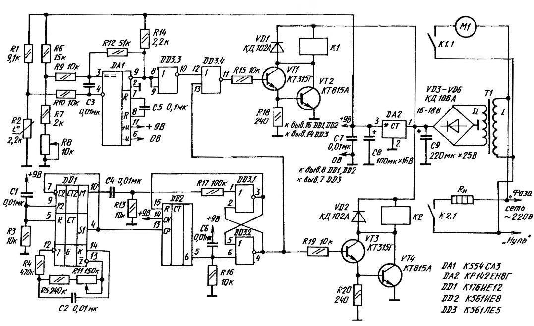
A circuit diagram of an electronic control device refrigerator (click to enlarge)
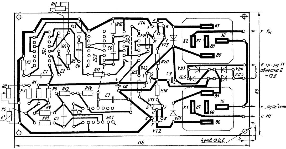
A printed circuit Board (click to enlarge)
The "heart" of timing of the device - the electronic unit on the chip DD1, includes a master oscillator and frequency dividers 32 768 and 60. Chip DD2 is an additional divider division 6. Logic elements DD3.1 and DD3.2 assembled RS-trigger, and the transistors VT3 and VT4 - current amplifier, the load of which is the relay K2. Through the contacts of K2.1 includes a heating element RM of activates.
The job of the thermostat is based on a comparison of voltages taken from the shoulders the measuring bridge, having in its composition sensor - thermistor R2, the signal from which is supplied to the input 4 of the comparator DA1.
From the output 9 of the comparator signal of the temperature arrives (via the node lock logic elements DD3.3 and DD3.4) to the input of the current amplifier, which is made on transistors VT1 and VT2. Load here is the electromagnetic relay K1. When temperatures above the threshold set by the variable resistor R8, the output 9 the comparator sets the voltage of high level. Transistors (VT1, and then and VT2) are opened, causing the relay K1, which contacts K1.1 connects to the AC motor M1 of the compressor. Temperature in the fridge will be reduced, causing an increase in resistance thermistor R2.
The last achievement of the threshold, the comparator is triggered, and its the outlet 9 is set to the low voltage level. Transistors VT1 and VT2 the current amplifier is closed. Relay K1 releases its armature, thereby opening the contacts K1.1 in the power supply circuit of the motor M1 of the compressor.
Resistors R9 and R12, providing hysteresis for DA1, contribute to a clearer the work of the thermostat. Voltage 9 V power measuring bridge and comparator stabilizes the chip of DA2.
The capacitors C3 and C5 noise. Resistor R14 serves as the load of the open the collector of the comparator, a R15 limits the base current of the transistor VT1. Blocker (DD3.3 and DD3.4) disconnect the thermostat from the current amplifier at the time the heating element RH of activates. The shunt diode VD2 voltage spike self-induction in the coil of the relay K1 at the time of the closing of the transistor.
The basis of timing of a part - timer on chips DD1 and DD2. When you turn supply voltage DD1 chip set - via reset circuit RЗС1 - in zero (the log. 0) and R6-trigger - through the chain R16С6-in one state (the log. 1). Then the output 4 DD3.2 and input 2 DD3.1 will log.Oh, and the output 3 DD3.1, connected to the reset input I chip DD2, - log.1. The counter-divider with this is cleared to zero count.
The master oscillator in (DD1 chip, the resistors R4, R5, R11 and the capacitor C2) produces pulses from 175 to 280 Hz. The frequency is changed variables resistor R11. The period of oscillation pulses of the generator at the middle position engine R11 is about 4,58 MS. Resistor R4 limits the current discharge of the capacitor C2.
Through connections inside the chip DD1 pulses of the master oscillator G are transmitted to a divider CALENDAR. In this case, the period of generation increases to 32 768 times and the output S1 is a signal with the oscillation period of 2.5 min. Last, acting on the input of C2 DD1 chip, is divided into 60. Thus, the output M chip 001 produces pulses having a period equal to 2.5 hours
From the output of the M chips DD1 first positive differential voltage appearing after approximately 1.5 h, passes through the differentiating circuit R13С4, resistor R17 and acting on input 1 logic element DD3.1, this switch RS-trigger. Output 3 DD3.1 there is a voltage low, and the output 4 DD3.2 - the voltage is high. Last through the resistor A opens the transistors VT3 and VТ4 amplifier current; relay K2 is actuated and the contacts of K2.1 connects the heating element RL to mains.
High voltage taken from the output 4 DD3.2, is applied to the input 13 lock DD3.4, which, acting on the input resolution of the signal, closes the VT1 transistor, whereby the thermostat is disconnected from of the current amplifier.
At the same time, the voltage of low level is supplied from the output 3 DD3.2 to the input I chip DD2, enables the frequency divider 6. The pulse S1 served on DD1 CP chip DD2. Then at pin 5 of the chip signal obtained with period of 15 min, which, acting on the input 6 DD3.2, switch R6-trigger, and output 4 DD3.2 there is a voltage of a low level. The transistors 1 and VT VТ2 closed, relay K2 releases the armature and contacts To 2.1 disables heating the element of RL activates from the mains.
The signal received at the input 13 DD3.4, is applied to the enable input. The lock opens and the thermostat is connected to the current amplifier. Dividers on chips DD1 and DD2 are set to zero, and R6 is a trigger in single state.
With the advent from the pin 10 DD1 the next pulse, the positive difference which in the steady state is repeated every 2.5 hours, will be activatel turn on for 15 minutes To power the device from AC power the 220 has a built-in adapter with step-down transformer T1. rectifier bridge VD3-VD6, 9-volt voltage regulator and DА2 capacitive filter C7-C9.
All components of the device (except the transformer T1, thermistor type R2 MMT-1, and variable resistors R8 and R11 type JS4-1) mounted on the PCB size 118x65x1,5 mm of one-sided foil fiberglass. Fixed resistors type MLT-O. 125. As capacitors C1-C7 recommended K73-9, and S8 and S9 - electrolytic K50-16. Semiconductor diodes - silicon: CDA (VD1, VD2) and CDA (VD3-VD6).
Transistors also silicon. At the inputs - CTG with the possibility of replacing on CTA (VT1 and VT3), then the output - CTA or CTA (VT2 and VT4), installed vertically, without radiator. Chip: DA1 - CSS, DA2 - KING, DD1 - KIE, DD2 - KIE, DD3-CLE.
Electromagnetic automotive relay type 113.3747-10, which powerful contacts easily withstand repeated inclusion of compressor motor M1, and the heating element of DH activates. The transformer T1 power 2-4 W (used in many adapters industrial manufacturing).
Debug assembled PCB is disconnected from the fridge condition. Instead of the load (the motor M1 and the heating element RL) uses ordinary table lamps.
Expansion of the device to be responsive to change temperature in the range from minus 14 to plus 4°C. However, to deal with the cold when debugging electronics difficult, so it is recommended to replace the regular R8 resistor of 1.5 kOhm. Then align the thermostat can be performed already available for this range: plus 18-40°C. And to accelerate tuning works on the timing of the device is recommended to reduce the capacitance of the capacitor C2 a hundred times, then the period of the pulse output from the M chips DD1 will be reduced to 90 C.
Checked and adjusted the device (after the restoration of the elements, required by the scheme) to be mounted in the refrigerator.
Author: G. Skobelev