Yes, fans of aquarium fish, care of regular feeding your beneficiaries it is possible to entrust described here the automaton. It provides daily disposable morning feeding fish.
The electronic part of such a device (Fig. 1) form the photosensitive element, the function of which performs a photoresistor R1, Schmitt trigger, assembled on the elements DD1.1 and DD1.2, driver the normalized pulse duration of feeding, performed on the elements DD1.3, DD1.4, and the electronic key on transistors VT1,VT2. The role of the pipette feed performs a solenoid driven with a transistor key.
The power source of the machine is commercially available rectifier RM-1, intended to power the engines electrified self-propelled models and toys, or any other AC adapter with an output voltage of 9 V and a load current up to 300 mA. To improve the stability of operation of the machine the photocell and the chip is powered by a parametric voltage stabilizer R7, VD2, C2.
In the dark, when the resistance of the photosensor R1 is large, the input and the output of the Schmitt trigger and the input element DD1.3 and the exit of the element DD1.4 has a low voltage level. Transistors VT1 and VT2 are closed. In this "standby" mode, the device consumes a small current is only a few milliamps. With the dawn the resistance of the photoresistor starts to decrease gradually, and the fall the voltage across the resistor R2 increases. When this voltage reaches the threshold trigger, the output of the element DD1.2 appears the high signal through resistor R5 and capacitor C3 is input to the element DD1.3. As a result, the elements DD1.3 and DD1.4 shaper normalized pulse duration switched in the opposite logic state. Now, the signal of high level at the exit of the element DD1.4 opens the transistors VT1 and VT2, and the electromagnet Y1 actuating actuates the feed dispenser of fish.
With the onset of evening wear resistance of the photoresistor increases, and the voltage on the resistor R2 and, consequently, at the input of the trigger decreases. When the threshold voltage of the trigger switches in the initial state and the capacitor C3 is quickly discharged through the diode VD1, resistor R5 and the element DD1.2. At dawn the whole process works the machine is repeated.

Fig. 1 (click to enlarge)
The duration of operation of the dispenser is determined by the time charging of capacitor C3 through resistor R6. The change of the resistance this resistor regulates the norm pour into the aquarium feed. To the device did not work with the loss and the subsequent emergence of mains voltage, ambient noise, in parallel with the resistor R2 is connected to the capacitor C1.
DD1 chip can be CLA, transistor VT1 - CTA-CTI, CTE-KHV, CTA-CTA,//T2 - CTA, CTB, CTA, CTB, CTA-CTG, CTA - CTG. Zener diode CSA to replace XA, XV, XV. Diodes KDB - KDA, KDA, KD102B KDA, KDB, DA, D. Capacitor C1-km; C2 and C3-C50-6, K50-16, C4 - C50-16 or K50-6. Trimmer resistors R2 and R6 - CP3-3, other resistors - th, MLT. Photoresistor R1-SF-2, SF-5, SF-6, SF-12, SF-16; you can also use the phototransistor FT-1.
Circuit Board together with the photoresistor stir in a plastic housing of a suitable size. In the housing wall against the photoresistor drill hole. The device is put on the windowsill so that through the hole in the housing on the photoresistor fell diffused daylight and not in direct sunlight or light from artificial light sources. To connect with block supply and the dispenser housing can be installed in the connectors of any design.
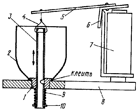
Possible design of the dispenser installed the aquarium shown in Fig. 2. For the purpose of simplification, the function of the electromagnet in it performs several altered electromagnetic relay REN-18 (passport RH.564.706), which is triggered at a voltage of 6 V and provides sufficient force for operation of the dispenser.
The dispenser consists of a conical hopper 2 of thin metal (you can use the body from the aerosol drug) attached to the cylindrical base 1 thick 5...7 mm and a diameter of 15 to 20 mm. At the base - through hole with a diameter of 5...7 mm, in which freely moving thin-walled the tube 3 with a metering hole in the wall. Bottom on the tube wearing spring 9 that is fixed by a washer 10 and the flared (or melted - for plastic tube) end. The upper end of the steel tube wire rod 4 is connected to the lever 5, is bonded to the anchor 6 relay 7. All relay contacts are removed. The hopper and rigidly relay fastened to the base 8 of the dispenser.
Dry food is poured into the hopper. At the time of dosing the hole in the tube, the diameter of which is equal to the stroke length of the tube under the action of the relay armature should overlap the base of the bin. When a relay is anchored via the lever 5 and the craving 4 displaces the tube up, the metering hole in the tube is opened and through it food hits the aquarium.
Establishing automatic in that order. The engine resistor R2 install the top (the scheme) position and place the device at the selected location. In the morning, with a small light, slowly increasing the resistance of this resistor, achieve actuation the pipette. Later in the hopper feed and fall asleep, occasionally obscuring the photoresistor, a trimming resistor R6 regulate the duration of operation of the dispenser.
The operation of the device in the automatic control mode within two to three weeks and spend additional required adjustment.

Fig. 2
Author: I. Nechaev, Kursk; Publication: www.cxem.net


