


")

One of the main conditions for successful cultivation of flowers and vegetables in greenhouses - compliance with the necessary light conditions. It can also be achieved automatically the device, which is described in this article. In addition to the greenhouses, it will find application for lighting aquariums, as well as in locations where it is necessary the extension of daylight, such as in poultry houses and livestock farms.
The proposed automatic "daylight" turns on the light at dusk and turns it off after a programmed time of daylight. which depending on the plant species can be adjusted in the range of 12 to 15 h with an interval of one hour.
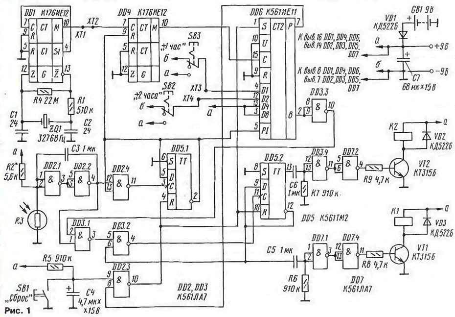
Schematic diagram of the automatic "daylight" is shown in Fig. 1. It consists of the master oscillator and frequency divider pulse on the chip DD1, frequency divider 60 on the chip and DD4 counter with pre the installation is made on the chip DD6, pulse shaper elements DD2.1, DD2.2 and the control unit.
(click to enlarge)
The time of daylight is programmed by setting the code on the meter DD6. The minimum time is 12 h (both switches shown in the diagram position). This time can be increased by 1, 2 or 3 hours turning on and SB2 (or) SB3. Real time less than 21 min, as the first on the front the output DD4 occurs later, 39 minutes after reset.
After switching on the voltage at the input 9 of the element DD2.3 will be to present the level of the log. 0, and its output is the level of the log. 1 that resets triggers DD5.1 and DD5.2 and pre-setting the counter DD6.
Crystal oscillator and the frequency divider pulses on a chip DD1 start to work immediately after the submission to them of the supply voltage. With output 10 chip DD1 pulses with a period of 1 min is input From the frequency divider 60 chip DD4. However, the counter starts until the account because the input R chip DD4 and the carry-in input PI counter with DD6 pin. 2 trigger DD5.1 served prohibiting the level of the log. 1.
In the dark resistance of the photoresistor R3 resistance more resistor R2 and therefore the conclusions 1, 2 of the element DD2.1 chip voltage DD2 exceeds the switching threshold of the chip, and the counting input of the trigger DD5.1 - log. 0.
In the morning when the light increases, the resistance of the photoresistor R3 decreases and a terminal voltage of 1.2 element DD2.1 also begins to decrease. When it comes to voltage switching element DD2.1, the chain D02.1, DD2.2, DD2 4 transitions to another state. This process is accelerated by positive feedback through the capacitor C3 Trigger DD5.1 switches on it the inverted output appears in the log. 0, which enables the counters DD4 and DD6, and also prevents the passage of pulses through the element DD2.4. Every hour the counter state DD6 will decrease by one.
When starting the unit in the level 4 and 8 meter DD6 1 is written. Proinvertirovanny element DD3.3, it prevents the passage of pulses through DD3.1, and the trigger DD5.2 in the morning can change your status.
A minimum of five hours at the exit 8 DD6 will log. 0, input 2 DD3.1 - log. 1. It will permit the passage of pulses from the shaper DD2.1, DD2.2 to the input With trigger DD5.2.
In the evening when natural light is reduced, the resistance of the photoresistor R3 increases. Then on the pin. 3 element DD3.1 level appears log. 0, and the counting input 11 of flip-flop DD5.2 - the level of the log. 1. As a result, the trigger will change its condition and close the element DD3.2 for the passage of pulses. Further changing the illumination of the image sensor will not affect the operation of the machine until until the set time.
After status change trigger for pin. 13 item DD5.2 will be level log. 1, which will go to the differentiating circuit C6R7. From the output of the DD7.2 pulse with a duration of 0.6 s through the resistor R9 will go to the base of transistor VT2 and will open it. Work relay K2, and through the closed contacts of K2.1 will do power to the starting relay circuit (Fig. 2). When triggered, closes the contacts KZ. 1 - K3.4. Contact K3.1 block relay K3, and K3.2 - K3.4 (depending on the position of the switches SA1 - SA3) connects a particular line of light EL1 - EL3.
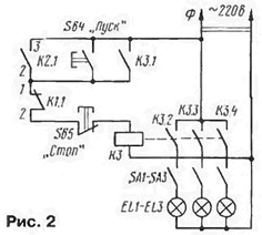
After a set number of pulses at the counter DD6 will be deducted, on its carry output R will log. 0. The input S of the counter DD6 and R inputs triggers DD5.1 and DD5.2 through the element DD2.3 to be filed log. 1. This will lead to the preset counter and the reset of the trigger. Differentiating chain and C5R6 inverters DD7.1, DD7.4 is formed by the pulse light is turned off, which will open the transistor VT1. Work the relay K1, and Rusakovskaya contacts To 1.1 disconnect the relay circuit. The contacts K3.1 - K3.4 will open, and the light will turn off. This happens at night and in the morning the work cycle of the machine again.
When working in the greenhouse, it is sometimes necessary to extend the time lighting is easy to do using the buttons SB4 ("start") and SB5 ("Stop"). On completion of work and turn off the light press on button SB1 ("Reset") to install the machine to its original state. After installation machine with the same purpose also it is necessary to press this button in the dark days. Daytime under low light, the light can be turned on manually, but before I leave greenhouse, if you have enough light, it should turn off.
As a source of backup power is used battery "Krona", connected to the main source through the diode VD1. At a current consumed in mode accounts for about 0.5 mA (relay - 20 mA) backup battery enough for the entire growing season of vegetables.
The photoresistor is better positioned in such a place greenhouses, where at night it not falling moonlight and the light from car headlights.
Establishing device start with test generator and frequency dividers pulse on the chip DD1. This can be done even the avometra by examining the second pulse at pin 4 and the minute pin 10 of the chip DD1. Next check the signal at pin 4 of the element DD2.2. For this light cover from the photoresistor R3 and choose such resistance resistor R2, in which the output level is set to 4 log. 1. The resistance of the resistor R2 depends on the selected light level at to trigger the machine.
After that you should unlock jumper between contacts 1 - HT and contact HT to connect with the pin. 4 DD1. In the presence of frequency counter with on / off input of it and should be connected to pin 9 IC DD4, and the counting input for contact HT. Then you need to include a table lamp and close the light from the photoresistor. On end of the frequency counter should display the number equal to put on the installation inputs of the counter DD6 and expressed in minutes. If the frequency does not has a start-stop input, the counting input connected to the output 10 of the chip DD4, but then highlighted the number will be expressed in hours.
In the absence of frequency in the moment of switching on the table lamp you need to detect time accurate to the minute, and the minute number of pulses applied to counter DD6, must equal the number issued in binary code on it installation inputs. For reliable detection of the stopping of the counter (on eyes) in parallel to the relay coil K1 through a 1kω resistor connects the red led. After graduating from the functional test device, you should restore the jumper between pins 1-HT.
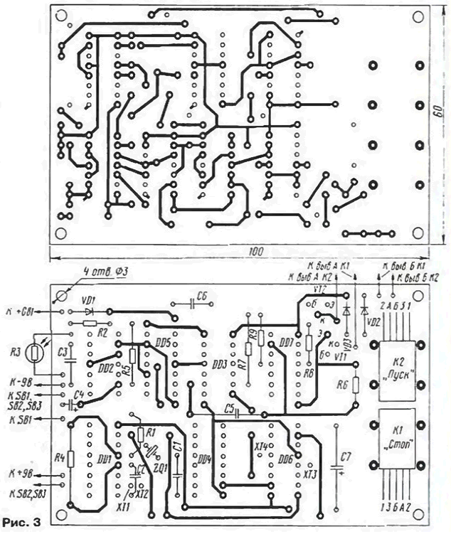
The machine is mounted on a printed circuit Board of foiled fiberglass 1.5 mm thick dimensions 100x60 mm. species from the printed conductors and from the parts shown in Fig. 3.
(click to enlarge)
The device incorporates resistors MLT-0,125. Capacitors C1 - C3, C5, C6 - km-6, C4, C7 - K53-1. Transistors KT315B interchangeable with any low-power silicon the structure of n-p-n with a valid collector current of at least 100 mA.
Chips instead of CIE (DD6) suitable KIE (for accounts in binary mode her pin. 9 must be connected to the circuit +9), CLA (DD2, DD3. DD7) and KTM (DD5) interchangeable similar chips series C. Relay K1, K2 RAS passport RS4.569.426. Many years of their operation showed stable operation in the machine. These relays can be replaced by RAS passport RF4.500.341 RES15 or passport RS4.591.003. Switches SB1 - SB3 - P2K.
Photoresistor R3 used by the author from the optocoupler OAP, from which it is removed light, and the photosensitive layer with epoxy. Optocoupler OAP contains two photoresistors (vyv. the 2.6 and 3.5), it is better to connect in parallel. It is permissible to use any other photoresistor, stating that its tuning (as mentioned above) the selection of the resistor R2. Connective the wire to the photoresistor length of 1 m must be shielded. Quartz the resonator ZQ1 - RC, it is possible to replace any faulty quartz hours, and if the frequency is two times lower, then the pin. 7 DD1 chip should to not connect with the pin. 4, and pin. 6.
The relay is attached to the PCB with two copper brackets, and quartz crystal set through the rubber gasket.
Cost is best placed in the shielding housing.
Author: N. Zaets, p. Veidelevka Belgorod region.