In many suburban areas and in rural houses have tanks, level water in which you have to periodically check and maintain, including the pump, forcing or pumping water. These operations are difficult to automate.
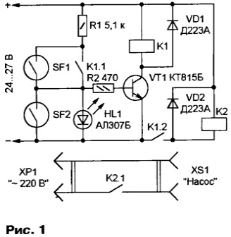
A diagram of the machine shown in Fig. 1.

The water level sensor in the tank to be arranged in such a way that the contacts of the reed switch SF1 is closed, if the level below the minimum, a SF2 - closed if it reaches the maximum valid. The key on the VT1 transistor controls an intermediate low-power relay K1. Relay K2 is a more powerful Executive. The led serves as an indicator HL1 the state of the machine. Diodes VD1 and VD2 extinguish the switching surges on the windings of relays. To power the device, you can use any DC voltage +24...27 V, providing a load current up to 200 mA.
If the contacts of the reed switch SF1 closed, the VT1 transistor opens, the relay K1 activated and its contacts K1.1 closes the circuit that supports the transistor in the open state and after the contact opening SF1. Through the closed contacts K1.2 supplies power to relay K2, which, in turn, includes the electric motor of the pump, forcing water. HL1 led is lit, signaling that the command to activate the pump served.
Upon filling of the vessel up to the level of actuation of the reed switch SF2 contacts last shunt the base circuit of the transistor VT1. The transistor is closed, relay K1 and K2 de-energized, disconnecting the pump from the mains. HL1 led goes off. Device remains in this state after time contiguity of the contacts of the reed switch SF2, while | the liquid level in the tank falls to such back work the switch SF1.
In the machine used resistors - MLT, reed switches - MQM MPAS P-2 (security alarm) relay K1 - RES-9 (RS4.524.200), K2 - RMU (RS4.523.330). All elements can be replaced with other similar parameters. Installation perform a hinged manner. The entire device, except the switch is placed in the body suitable sizes of insulating material, the reach set water place and connected to the reed switches three-wire cable.
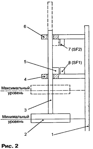
One possible design of the level sensor shown in Fig. 2.

The float 2 provided with a rod 3, sliding in the guide rails 4 and 6, mounted on the wall the tank 1. On the rod 3 is fixed a permanent magnet 5. If the water level the minimum or below, the magnet 5 is on the bottom rail 4 and its field triggers the reed switch 8 (SF1 according to Fig. 1). If the level maximum, magnet 5, reaching the upper rail 6, trigger the reed switch 7 (SF2). To use the machine to control the pumping of water from tank upon reaching the maximum level, it is enough to swap reed switches.
Author: B. Tatarko, Tver


