


")

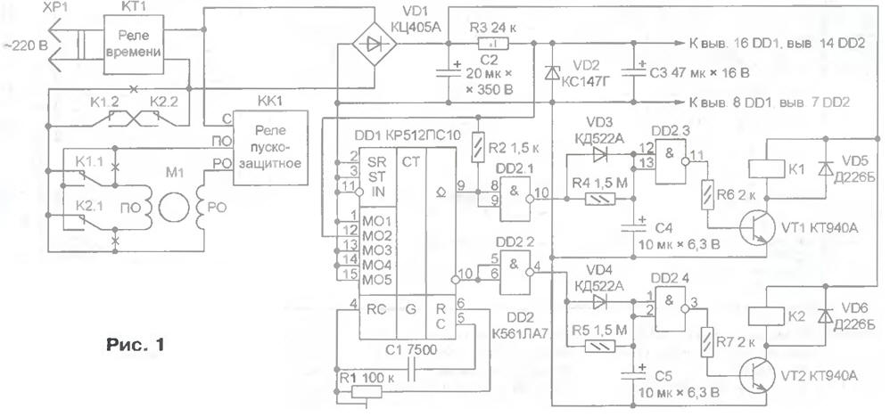
The circuit of the machine is shown in Fig. 1. The motor M1, protective and regulating relay CC and time relay CP1 - elements of the washing machine. Setting it automatic, you should cut a previously held connection at the points marked in the diagram by crosses places. As a result of improvements motor M1 is run by two newly installed relays K1 and K2.
(click to enlarge)
The relays K1, essentially restores the original connection, so the shaft of the motor M1 to rotate in the same direction as before the installation machine. When relay K1 is released and triggered K2 the direction of rotation will be opposite by changing the polarity of the starting winding connections BY the motor M1 to the network. Please note, the contact group K1.2 and K2.2 connected so that when the unused relays and their simultaneous accidental or due to a fault in the actuation of the motor M1 from the network is disabled.
The windings of the relays K1 and K2 nourishes the mains voltage, rectified by a diode bridge VD1. The output voltage R3VD2 (4.7 IN) is designed for integrated circuits DD1 and DD2. Capacitors C2 and C3 - smoothing. Diodes VD5, VD6 suppress emissions voltage of self-induction, appearing on the windings of relays K1 and K2 in moments closing of the transistors VT1, VT2, protecting the transistors from breakdown.
While the power is on, the internal oscillator of the chip DDI runs continuously, generating a pulse frequency of 1024 Hz. The connection of the control inputs m-M05 chip DD1 corresponds to the division ratio of the frequency 122880, and the period pulse on its conclusions 9 and 10 equal 122880/1024=120 s. Mutually inverse signals with these findings, having equal duration of pulses and pauses between them, fed to two identical node of the control relays K1 and K2, forcing thus, the motor M1 to change the direction of rotation.
Consider the work of one of the management nodes. The signal fed to its input, double-reverse the elements DD2.1 and DD2.3. Thus, in the log. 0 at pin 9 chip DD1 transistor VT1 is closed and the armature of relay K1 is released, with the log. 1 the transistor is open, the relay worked. However, the transition between these States happens at different speeds. In the first case, the capacitor C4 is quickly charged through the diode VD3, so the pause between the installation log. 0 at the input of the element DD2.1 and the release of relay K1 is almost there. In the second case, the charged capacitor C4 slowly discharges through resistor R4, the relay K1 is activated in approximately 10 after installation, log. 1 on pin 9 IC DD1. The delay is necessary to the motor shaft M1 before reversing the direction of rotation is done completely to stop.
The second management node (elements DD2.2, DD2.4, the transistor VT2) works similarly, but with a time shift by half a cycle. Full cycle (50 - rotation in one direction, with 10 - pause, with 50 - rotation in the opposite direction, 10 with another pause) is repeated until the time relay disable CP1 washing the machine from the network.
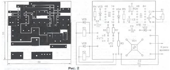
Almost all parts of the machine are mounted on the PCB size 55x60 mm sided foil fiberglass (Fig. 2). It is manufactured by the method cutting foil cutter. Since the power supply transformerless, he must be well isolated from the housing of the washing machine and protected from accidental touching. For this cost, it is desirable to place in a plastic the housing is mounted with relay K1, K2 inside the machine.
Chip DD2 CLA can be replaced by CLE. Diodes VD3 and VD4 on any of series KD522 or KD521, VD5 and VD6 - CDG or KD105B, a diode bridge VD1 - on CCW, CCJ or collect it from the diodes KD105B. Instead of transistors CTA suitable CTB, CTB. The C1 capacitor - mica K-11-3 with a tolerance of ±5 %. Oxide capacitors C2 - C50 -, C3 - C50-16 or K50-35, C4 and C5-K53-4 or K53-14. Relay K1, K2 RP-003-220 or C-004-220 and other Suitable relay operating voltage windings 220 having at least two switching groups contacts, capable of switching AC voltage of 220 V at a current of not less than 1 And, for example, MCU-WITH (passport RA.500.236, RA.501.148, RA.509.110).
When you first turn on the machine, you must install the trimmer R1 the required duration of the cycle. For as indicated on the diagram of the capacitance of the capacitor C1 position of the slider of the resistor should match the entered the impedance of about 65 ohms. After adjusting the engine securely, for example, a drop of paint. Even better, replace the trimmer permanent of that denomination. If between successive inclusions of the motor of the washing machine no time to stop completely or takes too long to rotate, pauses can be changed, picking up the elements of chains R4C4 and R5C5.
Author: E. Zuev, S. Dentino Vladimir region.