


")

The detector allows for a distance of 20 cm to detect any metal object. The detection range depends only on the square metal object. For those for whom this distance is not enough, for example the treasure hunters, it may be advisable to increase the size of the frame. This should to increase the depth of detection.
Schematic diagram
Schematic diagram of the detector shown in Fig. 2.50, and.
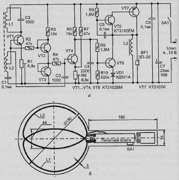
Fig. 2.50. A simple metal detector transistors: (a) schematic diagram; b - design of the metal detector
The scheme collected on transistors operating in the mode of micro, and consists of an RF generator (100 kHz) on VT1, which is configured by the resistor R1 to the maximum sensitivity to metal objects. As the coils L1 and L2 are two frames (Fig. 2.50, b). Transistors VT2, UTZ included as diodes ensure stabilization of the modes of the oscillator - VT1 and active detector on VT4 when changes in supply voltage and temperature.
Resistor R6 sets the sensitivity of the detector. Transistors VT5 and VT7 assembled an audio oscillator that turns on the transistor VT6. To ensure the loud sound of the piezo oscillator HF1, parallel to it included coil L3. This increases the voltage on the piezo oscillator due to the resonance between the inner capacity HF1 and inductance L3. When you hit the field coils L1-L2 metal object the oscillator frequency varies, which leads to a decrease the amplitude of the input voltage detector (VT4). It is locked, and the transistor VT6 opens that enables the sound generator.
The benefits of the scheme
This scheme compared to similar devices that use the principle the beating frequencies, provides greater sensitivity and easier to manufacture.
The power scheme of the detector
As the source power applied battery type "Corundum" or "crone" (9), but it can be used any stationary source with voltage of 6-10 V. Current consumption in standby mode 1.5 mA, while working beeps - 7 mA.
The printed circuit Board and the placement of elements
All schema elements can be placed on the PCB of unilateral fiberglass (Fig. 2.51). The casing for the frame need to be made of any dielectric materials, for example, to glue plexiglass.
The coils of
Coils L1 and L2 should be the same and contain 40+40 turns of wire PEL 0.25 mm diameter (perimeter coils 340 mm).
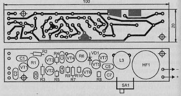
Fig. 2.51. The printed circuit Board
Coil L3 is wound on two ferrite glued together rings size K10 x 6 x 3 mm, grade 400 - 1000NM and contains 250-300 turns of wire PEL diameter OD mm.
Element base
Adjusted the resistors R1 and R6 should be type SP5-16B, the rest can be any compact. Capacitors C7 - type K50-35 to 16 In, and the rest type K10-17.
The VD1 diode can be replaced by any impulse. Micro switch SA1 type PD-9-2.
Setting of the metal detector
When you configure a device if you cannot get a generation at VT1 using adjust the resistor R1 (need to control the oscilloscope the voltage on this the resistor), you'll need to change the phase of the connection terminals of the coil L1.
When adjusting the circuit for maximum sensitivity to metal objects you may want to change the distance of overlap of the coils "A" (Fig. 2.50, b), then frame coils need to fix it with glue.
Publication: www.lib.qrz.ru