Schematic diagram
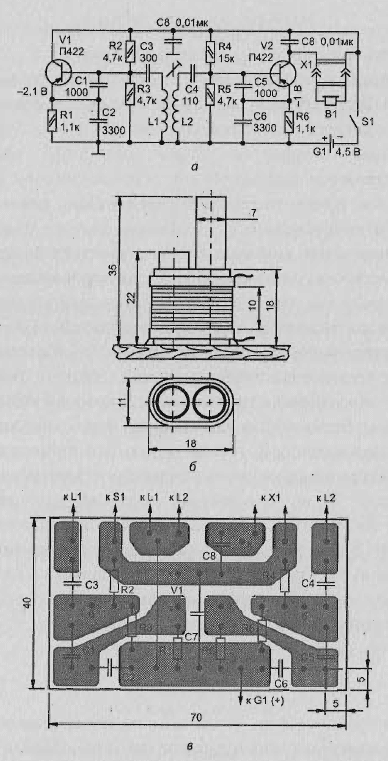
The scheme is simple transistor detector is shown in Fig. 2.5, and. It consists of a high-frequency generator and receiver, which registers changes the oscillator frequency when approaching him metal objects.

Fig. 2.5. Simple transistor detector: (a) schematic diagram; b - the L2 coil design; - printed circuit Board pattern
The receiver of the heterodyne detector type. He made only one the transistor V2, and combines the functions of a local oscillator and detector.
The local oscillator is built on a capacitive treatacne. The advantage of this scheme is the use of inductors without bends, which is very convenient for beginners radio Amateurs.
The resonant circuit includes an inductor L2 and the capacitance is composed of of series-connected capacitors C4-Sat. The frequency of the local oscillator can change setup the core of the coil L2.
A high-frequency generator is assembled on the transistor V1 is also capacitive scheme treatacne. The oscillator frequency depends on the inductance of the coil L1, which made in the form of frames. If near the coil will be a metal object, the inductance will change. This will result in a change of the oscillator frequency, will be immediately detected by the receiver. If, for example, originally the generator is tuned to the frequency of 465 kHz and the local oscillator of the receiver to the frequency 465,5 kHz, in phones to listen to the signal frequency of 500 Hz. When approaching coil L1 to the metal tone of the signal will change. This will serve as signal detection of a metal object.
Element base
In addition to transistors, indicated in the diagram, it is possible to use germanium transistors series P401, P.
Telephones - TONE-1 and TONE-2. Both the primer you want to include in parallel to the total resistance of phones amounted to 800-1200 Ohms.
All resistors can be MLT-0,125 or MLT-0,25, capacitors - KLS-1 or BM-2, power switch - single pole toggle switch.
Battery power - the three elements 316, 343, connected in series.
Coil
Coil L1 is a rectangular frame dimensions 175 x 230 mm 32 turns of wire sew-2 of 0.35.
The design of the coil L2 shown in Fig. 2.5 b. In two cylindrical paper frames placed segments of rod diameter 7 mm ferrite with permeability of 400 or NN:
- the first frame length 20-22 mm, is fixed permanently;
- the second frame length of 35-40 mm, movable, to adjust the coil. Frames wrapped with a paper tape, over which is wound coil - 55 turns of wire PELSHO 0,2 (sew-1 sew-2), the terminals of the coil is fixed with glue.
The printed circuit Board
The printed circuit Board pattern is shown in Fig. 2.5, V. Charge need to connect with coils, a battery, switch and connector X1 flexible stranded wire in isolation.
The coil L2 should be set to a distance of 5-7 mm from the turns of the coil L7.
The block X1 and the switch it is recommended to attach externally to the side wall case. On top of the case can be glued wooden handle length of about one meter.
Author: Vasiliev V.


