


")

During the city and field surveys surveyors and surveyors often to find a surveyor's marks. The latter are sometimes under a layer of soil, making their detection more difficult. If the organization has the underground stuff, there is a need to determine under a layer of soil or snow the location of manhole covers.
The device ISR-1, described below, is intended to facilitate the solution of these tasks. During the tests the device was discovered under a layer of soil points polygonometry at the distance of 0.3-0.4 m, the covers of the wells is at a distance of 0.8-1 m.
The principle of operation of the device ISR-1 based on the fact that the oscillator frequency is changed, if the search coil approaches a metal object. The closer the search coil to the metal object, the more increases the frequency generator. Therefore, registering somehow change the frequency generator, it is possible to find the metal object. The maximum the frequency change corresponds to the minimal distance between the search coil and a metal object. Changing the frequency of the generator can be registered in hearing (using the method of the beats), or visually.
If between the generator with an external search coil and amplifier constant current to include respectively configured FSS (filter centered selection), changing the frequency of the generator will vary the amplitude, and hence the collector current of the transistor T3. In the collector circuit T3 is enabled, the device 200 mA.
Schematic diagram of the device ISR-1 is presented in Fig. 1, and. Generator sinusoidal oscillations performed on the transistor T1 on the three-point scheme. The working point is determined by the voltage divider R1, R2 and the resistance R3. In addition to the relatively high stability of frequency, amplitude and good shape oscillations, the generator has another advantage: it uses nonpartitioned search coil. The variable capacitor C5 allows you to change the oscillator frequency from 430 kHz to 500 kHz. By changing the capacitance C5, you can choose the optimum location of the operating point on the frequency curve FSS (the area of greatest slope), this corresponds to a maximum the sensitivity of the device.
A sinusoidal voltage generator via the resistance R4 is supplied to the FSS, tuned to a frequency of 445 kHz. As the inverter amplifiers in radio receivers tuned to 465 kHz, the device is not working creates interference. The device uses the FSS used in the radio Atmosphere-2M". Using a setup cores reshaping its contours on the operating frequency of the device (445 kHz) without changing the winding of these coils. In the device can be used FSS and from other radios. Preferably apply contour coil high q, such as the FSS pocket radios "Topaz-2" and "Falcon".
The scheme shown in Fig. 1,b, differs from the first scheme (Fig. 1,a) additional second stages, which allows to obtain a higher the sensitivity of the device.
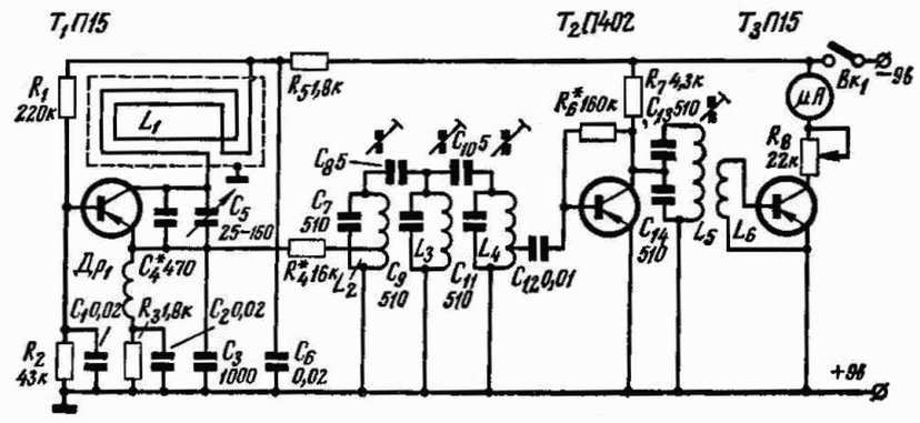
Fig. 1,and
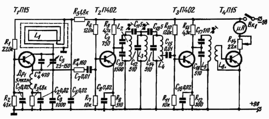
Fig. 1,b
The establishment of the unit. Correctly assembled the generator starts to generate at once, and his establishment consists only in the selection of such a capacitance of the capacitor C4, when which the oscillation frequency is approximately equal to 445 kHz. The rotor the variable capacitor C5 must be installed in the middle position. Frequency was measured device FS-7 through a resistance of several shortfall is connected to the output emitter of the transistor T1 and to a common positive the clamp. To configure the FSS required GSS-6 and measuring the output device sensitivity 200 µa). Configure similar devices described in the magazine "Radio", No. 8, 1960, p.22.
The search coil, which is an oscillatory circuit, must be placed in an electrostatic screen. It runs from dural tube diameter of 12 mm in the form of a ring with a diameter of 390 mm. On the outer circumference of the ring with a hacksaw saw through the cut and stack 14 turns of wire PELSHO of 0.28.
After laying the wire impregnated with paraffin and the entire ring wrapped with insulation tape or varnished cloth. The search coil is connected to the generator shielded coaxial cable which runs inside the tube. Like the ring itself, and the tube is connected to the positive terminal of the power source (two batteries BSC-0,5). They are located in a single housing with a microammeter. The knob (variable the capacitor C5) is derived to the outside through openings in the bottom and the housing cover the actual device. A variable resistor R14, connected in series with a microammeter, is used to adjust the sensitivity. When carrying the device the ring is pressed against the tube and fixed spring latch.
Basic dimensions the device shown in Fig. 2.
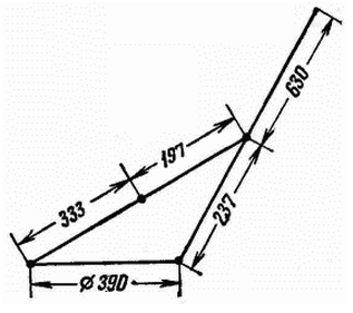
Fig. 2
The installation is made on a laminated bakelite Board (Fig. 3) size 100x75x2 mm.
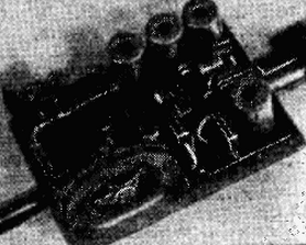
Fig. 3
Authors: A. Zotov, V. Kharin