


")

The detectors, which are based on the evaluation deviation of the beat frequency (BFO), have relatively low sensitivity when the search for metals with a weak ferromagnetic properties (copper, tin, silver and etc.). Because the difference frequency (beats) hardly noticeable during normal use methods of indication, to increase sensitivity metal detector BFO pretty difficult.
Naturally, this situation was a good incentive to find other circuit solutions. Many years ago the author was fabricated device, based on the original scheme of the device, published in the magazine "Radio-Electronics" (1967, No. 11). The main element by which the analysis was carried out in the presence of metal objects, was quartz. The results of the analysis were evaluated visually.
Schematic diagram
We offer our readers the design represents one of the options metal detectors of the type FM (Frequency Meter), then there is a device in based on the principle analysis of the frequency deviation of the reference oscillator under the influence of metallic objects caught in the area of the search coil. The main distinctive features of this device can be considered interesting schematic of the analyzer is performed on the quartz element Q1, and also use as an indicator of a pointer device. The basis of the scheme the considered detector (Fig. 2.15) are measuring the generator buffer amp, analyzer, detector and high frequency oscillations indicating instrument.
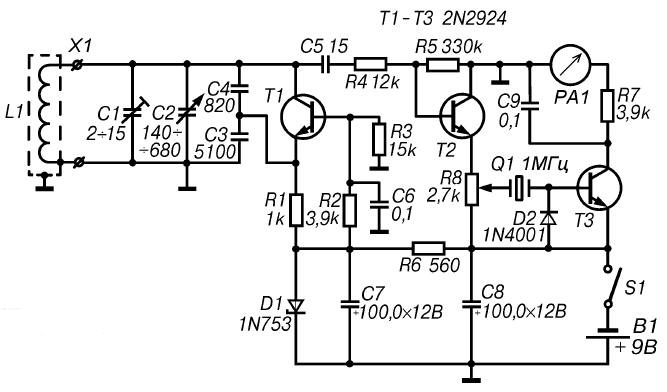
Fig. 2.15. Schematic diagram of the detector with quartz
The oscillating circuit of the generator of high frequency, performed on the transistor T1. consists of a coil L1 and capacitors C1-C4. The working frequency of the RF generator depends on the deviation of the inductance coil L1, which is at the same time search coil, and change tanks trim (C2) and adjustment (C1) capacitors. In the absence of metal objects in the range of a coil L1 frequency oscillations excited by a RF generator, must be equal to the frequency of the quartz element Q1, that is, in this case 1 MHz.
After near the coil L1 will be a metal object, it the inductance will change. This will lead to the deviation of oscillation frequency RF generator. Further, the RF signal is fed to the buffer cascade, providing coordination of generator with the subsequent circuits. As a buffer stage use the emitter follower is performed on the transistor T2.
From the output emitter repeater RF signal through a regulating resistor R8 and quartz Q1 is supplied to the detector made the diode D2. Due to high the quality factor of the quartz slightest change in frequency of the measuring oscillator will be to reduce the impedance of the quartz element. As a result to the input of the DC amplifier (UPT), performed on the transistor T3. enters low-frequency (LF) signal and changing the amplitude of which provides the corresponding deflection of the indicator device. Load UPT, performed on the transistor T3, is a pointer instrument with a current total deflection of 1 mA.
Food metal detector is from the source B1 voltage of 9 V.
Details and design
As discussed earlier in some designs, for the manufacture metal detector with quartz element, you can use any development Board. So used to detail without facing any restrictions associated with dimensions. The installation can be both mounted and print.
The search coil L1 is a circular frame, made of a piece of cable with an outside diameter of 8-10 mm (e.g. cable brand RC-50). The Central core of the cable should be removed, and instead lend a lived six wire type PEL diameter 0.1-0.2 mm and a length of 115 mm. the Resulting stranded the cable must be bent on a suitable mandrel into the ring so that between the beginning and the end of the formed loop has a gap width of about 25-30 mm.
The end of the wire, which is the beginning of the first coil should be soldered to the shielding the braided cable, the beginning of the second round by the end of the first, and so on. As a result get coil with six turns of wire. In the manufacture of the coil L1, it is necessary to ensure that did not happen circuit the ends of the braided shield, as in this case, a closed loop is formed.
Additional rigidity of the coil L1 can be given, if to have it between two discs of plywood or Micarta with a diameter of 400 mm and a thickness of 5-7 mm. Instead of transistors type 2N2924 indicated in the diagram, in this design it is possible to use virtually any domestic low-power silicon transistors for example type KT315B. Instead of the diode type part no 1n4001 (D2) is recommended any germanium diode series or D2 D9 with any letter index, and a Zener diode type 1N753 no problem to replace, for example, a Zener diode ZA.
As element Q1, you can use either a quartz element with a frequency of 900 kHz to 1.1 MHz. As the power source V1 can be applied, for example, the battery "Krona" or two batteries 3336L connected in series.
Board with the controls it contains and the power source are placed in any a suitable plastic or wooden case. On the housing cover set variable resistor R8, connector X1 for connection search coil L1, the switch S1 and the indicator PA1. The search coil L1 should be installed on the end of a suitable handle length 100-120 see Connecting the coil with the Board device is shielded stranded cable.
Establishing
The main condition for ensuring quality setting for this device is the lack of large metal objects at a distance of not less than 1.5 m from the search coil L1.
Direct the establishment of the detector should start with the desired the oscillation frequency generated by an RF generator. The oscillation frequency of the RF should be equal to the frequency of the quartz element Q1. To perform this adjustment it is recommended to use a digital frequency meter. In this case, the frequency value first roughly set by the capacitance change of the capacitor C2, and then accurately - adjustment of the capacitor C1.
In the absence of frequency-tuning RF generator may be indications indicator PA1. Because the quartz Q1 is an element of connection between the search and flat parts of the device, its resistance at the time of resonance is very great. Thus, the exact configuration of oscillation of an RF generator frequency quartz will testify to the minimum reading of the pointer device PA1.
The sensitivity of this device is governed by the resistor R8.
The order of work
In the practical use of this detector should be variable resistor R8 set the arrow indicator PA1 to zero. When this to some extent compensates for the change of operation modes, due to battery discharge, the change in the ambient temperature or the deviation of the magnetic properties of the soil.
If in the process of work in the area of the search coil L1 will be any a metallic object, the meter needle PA1 deviates.
Author: M. V. Adamenko