


")

Using a specialized chip CAM, digital multimeter can to turn in measuring temperature with high accuracy.
Digital multimeter DT830B bit depth of display 3.5 easily Supplement chip is a temperature sensor CEM. However, the output signal of this chip in the operating temperature range is in the interval 2331…3931 mV and measure its only at the limit of the voltmeter 20, and displayed on the display the temperature will be in °K.
The device described in the published article, is intended to reduce the output voltage of the chip KEM on 2731,5 mV. Transformed in such way the output voltage will correspond to the temperature in the usual °C.
An integrated circuit KEY and CEA [1, 2] represent sensitive sensors with a linear dependence of the output voltage from absolute temperature: Uвых=at.TC, where at=10 mV/K temperature coefficient voltage, TC is the absolute temperature in degrees K.
The accuracy parameters of the chips is quite high - accuracy output voltage of the chip is calibrated at +25°C, within just the operating temperature range of 45…+125°C does not exceed 10 mV, i.e., is less than 1°C and in the range 0…+40°C - 0.1°C.
In the apparatus described in the reference voltage source is used the internal ADC source of the multimeter. When you disconnected the sensor connector temperature power consumption does not exceed 100 μa, and when you connect sensor it is increased by the value of operating current of the chip CAM, of approximately 1 mA.
Schematic diagram of working with a multimeter (voltmeter) devices for measurement of temperature is shown in Fig. 1. It consists of extra cost A1.1 thermocouple A2. On an auxiliary Board mounted node the offset DC voltage, assembled by operational amplifier DA1 and transistor VT1. The magnitude of the offset voltage at the collector of transistor VT1 regarding output 32 ADC is 2731,5 mV. Trimpot resistor R1 is used for the exact setting of this value. Capacitor C1 adjusts the frequency characterization of the phase node voltage offset covered negative feedback through resistor R5, which eliminates the self. Transistor VT2 and resistors R11-R13 form a constant current generator to about 1 mA. The thermocouple consists of a chip-thermopatch CAM, resistors R8-R10 and the plug connector X1. Resistor R9 adjusts the output voltage of the chip.
Additional charge the device for temperature measurement multimeter DT830B made of plate unilateral fiberglass size 32x32 mm. The layout of this Board is shown in Fig. 2.
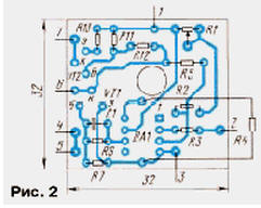
Once installed on Board all circuit elements and what you have! external conductors to the contact sites side-cutting pliers shorten their ends protruding from the printed conductors up to 1.5…2 mm, otherwise the fee is not located in the body the multimeter. Then, using bricks made from matchsticks, an additional fee is glued with glue "Moment" on a free site print Board multimeter. The thermocouple is also mounted on the circuit Board from fiberglass. Placement of the thermocouple elements shown in Fig. 3.
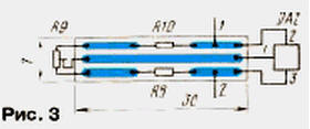
Open the pads and resistors thermocouple should be covered varnish or glue BF-2. The node of the thermocouple can be connected with the unit multimeter any two wire cable of the appropriate length. The author, for example, used telephone cable with a length of about 8 m. Features detachable connector perform a three-pole switching the plug from the stereo head phones with a nominal diameter of 3.5 mm and a three-pole switch socket 1308 MEK-PP.
In Fig. 4 shows a sketch of a three-pole plugs and sockets. Last set in drilled specially for her hole on the side the body of the multimeter. The plastic base of the socket should fit snugly to the plane of the body of the multimeter. For the strength of the connection of the glue, which is used in the manufacture of plastic models. Switching plug welded the conductor connecting 1 and 3 of its conclusions. This conduit connects measuring input terminal of the multimeter to the sensor only during the measurement temperature.
In measuring temperature applied trimming resistors SDR-19a (R1, R9), constant C2-29V (R2, R3, R5, R8, R9) and ALT (the rest). The Capacitor C1 ceramic of any type.
The device configuration sequence. First to the connector X1 connect the temperature sensor and the resistor R1 sets the voltage between the collectors of transistors VT1 and VT2 equal 2731,5 mV. After that temperature-sensitive transducer together with a medical thermometer placed under his arm, and after 5 minutes, compare the readings of the thermometer with readings on digital display multimeter set to voltmeter to the limit of 2000 mV. If these readings do not coincide, it is necessary to adjust the multimeter resistor R9. Then again measure the temperature and if necessary again make a correction. While achieving the same medical indications thermometer and multimeter setup complete.
In conclusion, it should be noted that the described device can be used in conjunction with any digital voltmeter based ADC CPU, CPV, CPW. The possible scope of its application is a remote temperature measurement inside and outside the dwelling and outbuildings, vegetable and grain stores, on the other objects requiring temperature control.
Literature
Author: V. Vorotnikov, Ekaterinburg