


")

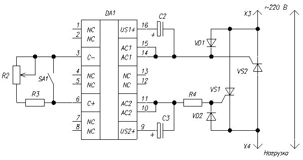
Thyristor regulator
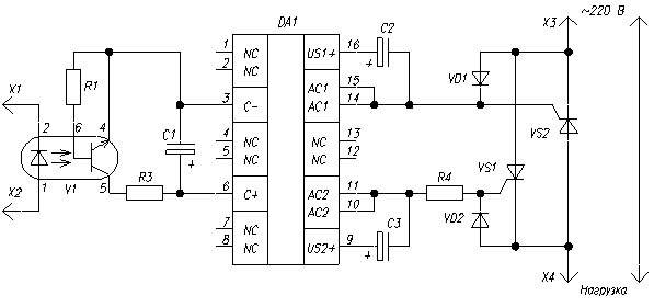
The device is designed for phase control of AC voltage on a resistive load. Can be used to control incandescent lamps, heating elements. When a certain combination of active and reactive component of the windings is possible to regulate the speed of rotation of the collector AC motors. Careful selection of capacitors forming the sawtooth voltage (C2, C3), with the aim of balancing the output voltage can ensure the operability of the regulator to the primary winding of the transformer with a resistive load in the secondary circuit.
Details
C2, C3 - K53-19-16V-1 UF±5% DA1 - CRM R2 - SP4-1A-0,5-mm±10% R3 - C2-23-0,125-3.3 ohms±10% R4 - C2-23-1-390±10% VD1, VD2 - CDD VS1, VS2 - COAThe controller parameters with the specified components in the diagram:
Input AC voltage, In 80…250 The load current, And 0…40 The range of output voltage regulation, % 90The device of smooth start
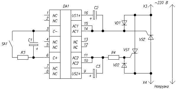
The device is designed for phase control of AC voltage on a resistive load. Can be used to control incandescent lamps, heating elements. When a certain combination of active and reactive component of the windings is possible to regulate the speed of rotation of the collector AC motors. Careful selection of capacitors forming the sawtooth voltage (C2, C3), with the aim of balancing the output voltage to ensure the efficiency of the regulator-General to the primary winding of the transformer with a resistive load in the secondary circuit.
Details
C1 - C50-53-16V-MK±20% C2, C3 - K53-19-16V-1 UF±5% DA1 - CRM R3 - C2-23-0,125-3.3 ohms±10% R4 - C2-23-1-390±10% VD1, VD2 - CDD VS1, VS2 - COAThe controller parameters with the specified components in the diagram
Input AC voltage, In 80…250 The load current, And 40The actuator system of regulation
The device is designed for remote control the power on the load. It provides galvanic isolation of the control part of the supply voltage. The controlling is performed by the discharge of the capacitor C1 or pulses or decent current flowing through the optocoupler V1. The control system can be built on the basis of the analog controller or PWM controller. It is also possible the use of microprocessor control. In this case, it is desirable to have a hardware PWM output the selected microprocessor.
Details
C1 - C50-53-16V-100mkf±20% C2, C3 - K53-19-16V-1 UF±5% DA1 - CRM R1 - C2-23-0,125-LM±10% R3 - C2-23-0,125-3.3 ohms±10% R4 - C2-23-1-390±10% V1 - AOTA VD1, VD2 - CDD VS1, VS2 - COAThe controller parameters with the specified components in the diagram
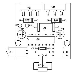
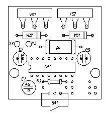
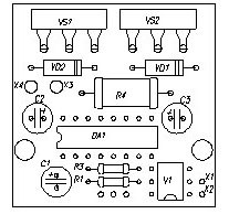
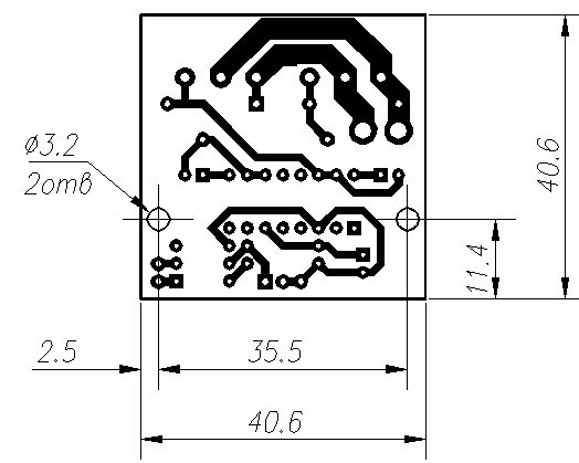
Input AC voltage, In 80…250 The load current, And 0…40 The range of output voltage regulation, % 90The universal printed circuit Board drawing (view from the PCB):
Universal printed circuit Board includes the installation of any components of all the above schemes without modifications. In the operation of devices with significant currents (more than 5 A) thyristors should be installed to the heat sink using thermal paste KPT-8. Instead CUA may use CU with any letter index or any thyristor series CO. If it is assumed the operation of the devices at lower currents, it is possible to use other devices, for example CU, CO, T-10, is designed for corresponding voltages. When installing the thyristors T-10 note that the order of their findings other than CU, CO, CU, CU.
Publication: www.cxem.net