Air temperature is an important environmental parameters significantly affect many of the processes of human life. So it continuous monitoring creates a definite convenience. The offered thermometer designed for indoor use and has a number advantages:
- first, it is powered by one AA battery, which never needs replacing during the year (assembled thermometer has been working for 8 months);
- secondly, it uses a digital temperature sensor. In this case achieved measurement accuracy of the order of ±0.5°C. a Digital sensor comes already calibrated, so the device does not require any additional configuration;
- thirdly, the connection of a liquid crystal display (LCD) directly to the microcontroller. In this mode, the consumed current indicator is about 10 μa, which is a positive continuous time battery life.
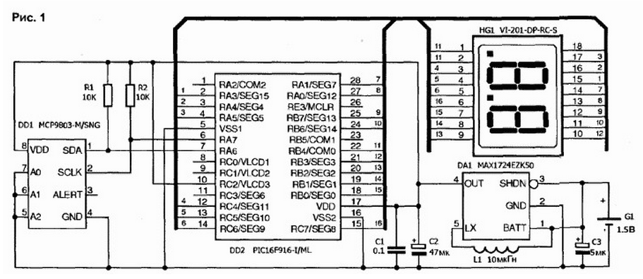
Thermometer (Fig.1) consists of four functional blocks.

(click to enlarge)
Temperature measured DD1 chip type MSR manufactured by Microchip. It contains a temperature sensor and a device that converts a value temperature-to-digital code with a resolution of 0.0625°C. This code is stored in the registers chip and may be requested by the microcontroller via the l2C interface. Resistors R1 and R2 serve to implement this interface. Operating range the temperature sensor is -40 to +125 C, which significantly overlaps the temperature range used LCD (-10 to +50°C). Therefore the range measurements of the thermometer is limited temperature range LCD. It should be noted, almost all LCD do not work at low temperatures without special heating. However, negative temperatures is very rare for residential premises.
The temperature is measured approximately once every 8 s. the rest of the sensor and the microcontroller is in the sleeping mode (the indications continue to be displayed), that significantly reduces power consumption. Digital code temperature is passed in the microcontroller DD2 type PIC16F916 for further processing and display on LCD HG1 (model VI-201 company Varitronix). The LCD has two digits for indication temperature and two decimal points. Left point is not used, and the right is to divide whole numbers and tenths of a degree from 0 to +9,9°C.
The temperature in the range from -9 to 0°C and from +10 to +50°C as shown only integer. The left digit LCD is also used to indicate a minus sign for negative temperatures.
In practice, the determination of the air temperature to the nearest fractions of a degree is sufficient for most applications. This allows to apply widespread LCD large size for ease of reading testimony.
The power from one AA battery is provided by the Converter voltage, made on the chip DA1 type MAH firm Maxim. Chip MAH available in several versions with fixed output voltages within 2...5 V. We have used a version of it at 5 V. However, the durability the battery can be improved by using a variant of the chip on the output a voltage of 3 V. the Sensor, the microcontroller and the LCD too can work from that voltage.
.The filter capacitors C2 and C3 required for normal operation Converter, and the capacitor C1 serves to suppress high-frequency ripple of the Converter and prevent the excitation of the microcontroller. A distinctive feature of the Converter chip is the lack of rectifier diode, typical of such schemes. This ensures a high level the efficiency of the Converter. Choke inductance L1 10...22 µh can to be almost any design, since power from the inverter current very small. We used the small choke SRU5016-100Y Bourns company.
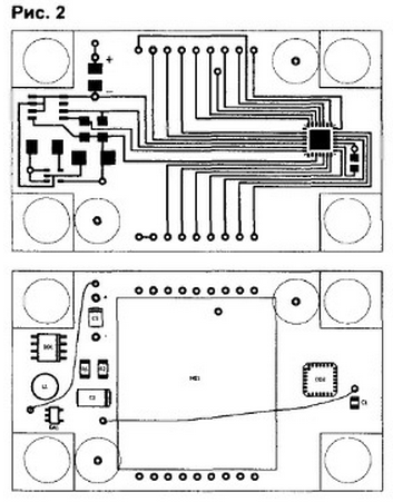
The printed circuit Board thermometer was developed under the chip MUCH in QFN. All other elements on the card is also designed for SMD-MOH-the same (surface). Resistors R1 and R2 can be in the buildings 0806 1206 or. Tantalum the electrolytic capacitors C2 and C3 is at a working voltage of 10 V, the capacitor C1 - ceramic in the body 0806. Circuits DA1 and DD1 - in packages SOT23-5 and S08 respectively. As DD1 is possible to use the sensor MSR. It available in 5-lead SOT23-5 is slightly smaller. This change will entail a slight correction the PCB, however, no changes in the code of the microcontroller is not required. The microcontroller can be replaced by PIC16F914.
The printed circuit Board was developed under the chip PIC16F916 in QFN and manufactured sided foil fiberglass dimensions 65x39 mm (Fig.2) back side of the PCB are two wire retainers, shown in layout. The shape of the PCB is designed to fit her in standard housing "JAL-1" size 68x22x42 mm. the case has two columns to fix the card with two screws In the side wall of the housing opposite the sensor temperature, the drilled hole 02 mm for better heat exchange.

The front panel is made of Plexiglas with a thickness of 2 mm and is secured with four screws to the corresponding counters of the body. At the bottom of the hull is glued to the holder for the battery AA. The battery connects on the PCB to the jacks marked "+" and "-". Because a low consumption current of the power switch is not provided.
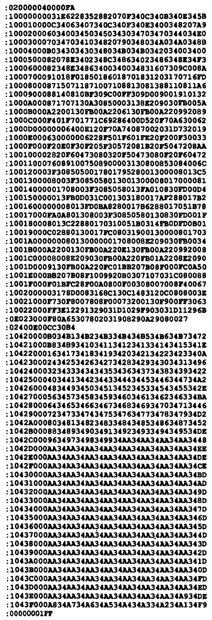
When assembling the thermometer on the first charge should be set by the microcontroller. Installation it is made by soldering with hot air. After installation you should write in it the program, shown in the table.

(click to enlarge)
For programming you can use any the programmer is connected via a 5-wire ICSP cable. Cable temporarily connected to leads of the controller through the slot installation of LCD on the Board. Long print path, is connected to pin 26 (MCLR pin), is designed for convenience soldering the corresponding wire ICSP cable. After programming this the track is no longer used, and a socket for connection of the wire remains closed-panel LCD.
Correctly assembled the thermometer in adjustment is not needed.
Authors: Sergei Bezrukov, V. Artists, Superior, USA


