


")

When growing seedlings and plants in greenhouses or on heated soil is important constantly to maintain temperature within specified limits. This function successfully performs automatic thermostat, electric contact is made on the basis thermometer with outside 0-50°.
(click to enlarge)
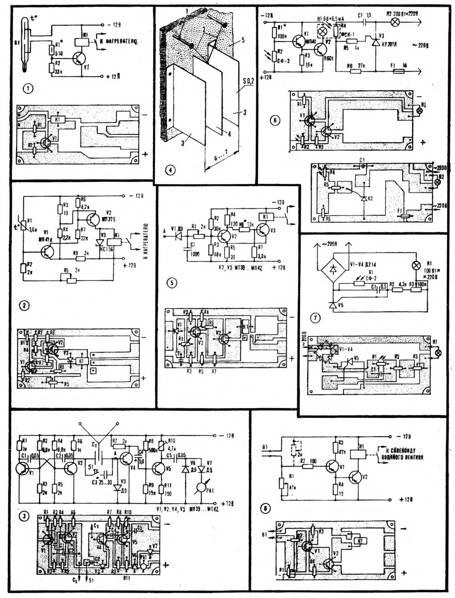
Fig. 1. Schematic and wiring diagrams thermostat on the basis of contact thermometer
Fig. 2. Schematic and wiring diagrams of controller-based thermistor
Fig. 3. Schematic and wiring diagrams of the moisture meter
Fig. 4. Device humidity sensor: 1 - nail 2 - human hair, 3 - fixed plate, 4 - movable plate, 5 - base
Fig. 5. Schematic and wiring diagrams of automatic controller consoles humidity level
Fig. 6. Schematic and wiring diagrams of the first embodiment light-dependent controller
Fig. 7. Schematic and wiring diagrams of the second light-dependent options controller
Fig. 8. Schematic and wiring diagrams of automatic watering
The principle of operation is simple. When the temperature drops below the set value, triggered electronic device transistor VI (Fig. 1) and contact system relay K1 mku-48 includes heating elements - heating elements with a power of 0.5-1 kW or heaters with mirror reflectors.
Relay mku-48 must operate at a voltage of 12 V, so it need winding rewinding wire sew 0.18 to fill the frame. With the help of resistor R1 set the current through the thermometer value is not more than 15 mA. As V1 you can use any medium power transistor (P4, P - P, P, P-P).
Instead of contact thermometer you can use a thermistor (for example, MMT-1). However, the electronic part of the second version of the controller more complicated. Thermistor R1 (Fig. 2) included in the shoulder of the bridge consisting of resistors R2 - R5. Potentiometer R5 govern the operation of the device within +15-60° and respectively graduate scale.
In the automatic device applied relay RES-10 (passport RS4.524.314) at establishing it will loosen the spring anchors.
To store seeds and fruits, to grow certain types of plants only if specific humidity. That is why in the private economy or summer cottage need a moisture meter. A variant of such a device is made on the basis of a device for determining quantities of small containers (3-30 pF), but it is the measured capacitance is mounted humidity sensor (Fig. 3). It consists of two copper (preferably plated) plates with an area of 15 cm2 each, fixed at a distance of 6-7 mm from each other on a rigid base with a minimum thickness of 2-3 mm, made of insulating material (plated hardened paper, glass fiber, plexiglass, plywood). Between these two plates on human hair suspended from the third, made of the same metal (Fig. 4).
The length of the hair is adjusted depending on the type microammeter: more sensitive than dial indicator, the shorter hair. For example, for the device with the scale of 25-50 µa hair length is approximately 40 cm.
The moisture meter should be graded on identical industrial - maximum the deflection corresponds to 100% humidity, the minimum is 10%.
Capacitor C3 is used to check the device and has such a size that when it is connection (without sensor) the needle of the microammeter deviated maximally.
Redefining the meter, it is easy to convert the machine to maintain the desired humidity. The circuit denoted by the letter A (see Fig. 3), is connected trigger with electromagnetic relays (Fig. 5). Variable resistor R1 sets trigger level automatic device to a specified percentage of humidity.
With increasing humidity the voltage of the rectangular form, flowing through the diode V1 charges the capacitor C1 to the level that opens the transistor V2. Triggered the trigger and the contact plate relay K1 turns on the fan. When the humidity is reduced to a predetermined level, V2 is closed and the trigger disables the relay K1 RES-10 (passport RS4.524.314). At setting it is necessary to weaken the springs.
Seedlings and early vegetables require for normal development of certain light. Provide light-dependent regulator (Fig. 6). With the onset of twilight resistance of the photoresistor R2 increases, and the transistor V1 is gradually is closed and V2 is opened. Lamp H1 is illuminated depending on the current flowing through the semiconductor triode V2, changes Accordingly the resistance of the photoresistor R4 in the circuit of the control electrode of SCR V3, thus regulating the light intensity. The total power of the lamps depends H2 type triode thyristor.
The device is assembled on two separate circuit boards installed side by side so as lamps are H1 and photoresistor R4 formed an optocoupler pair, they served opaque cap.
If we need to set a specific light level, collect automatic with manual intensity control of incandescent lamps. It is made on the variable resistor R3 (Fig. 7). Control voltage comes with divider, consisting of a photoresistor R1 and resistors R2, R3, silicon controlled rectifier V5. When R1 dimming its resistance increases, and the voltage drop across it increases. As a result of SCR V5 is opened stronger, lamp H1 is illuminated brighter. Capacitor C1 smooths out the pulsations of the rectified voltage. Photoresistor SF-2 can be replaced by any similar type (for example. FSK-1 FSK-2).
Moisture-loving plants require that the soil was always moist enough, but not excessively. It also helps in automation. Consisting of two transistors V1, V2 (Fig. 8) electronic device - humidifier soils associated with stuck in the ground sensor - two plates of stainless steel, of a width of 20-25 mm. the Length of their depends on the depth of soil moisture, and the distance between the plates choose experimentally - it largely depends on the type of soil. Junction wires from the sensor must be covered with waterproof paint.
Trigger level auto set variables resistor R1, through which the contact blades of the relay K1 includes a solenoid, associated with the valve controlling the water flow.
The trigger level of the instrument limit (to prevent waterlogging soil), continue the sensor is a variable resistor (shown in the diagram by a dotted line).
The device can be applied to the transistors MP-12 MP (V1), and V2 will fit any semiconductor medium power triode (A4, P-P, P, P - P). K1 - relay PCM-2 (passport 1017.181.02).