


")

By combining inductors and capacitors, it is possible to build filters first, higher order (the order of the filter is usually equal to the number of his reactive elements), i.e. having the steeper slopes of the frequency response in the band containment, and secondly, contributing to significantly less attenuation in the band transmission. In the ideal case, when the coils and capacitors have losses (infinite q-factor), LC-filters do not make losses.
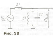
The simplest LC-filter - resonant circuit. Included on the on Fig. 38 the scheme, it will act as a narrowband bandpass filter, tuned to a frequency
f0= 1/2π√LC.
At the resonant frequency the impedance of the circuit is active:
R0 = pQ.
where p is the characteristic impedance equal to the reactive impedance coil and capacitor. It may be easier to calculate by the formula
R = √L/C.
Since the capacitor is usually almost not making losses, quality factor of the circuit is equal to the quality factor of the coil. Easier to determine resonance frequency and q-factor of experimentally gathered cascade on the above scheme. You will need a signal generator that generates the input voltage Uвх, and measuring the output with a high internal resistance, preferably an oscilloscope. It will serve to register the voltage Uвых.
By changing the frequency of the generator, be able to register the maximum Uвых on the resonant frequency of f0 contour. The resistor R1 and the resonance impedance of the circuit r0 form a divider, and
Uвых = Uвх/(R1+r0).
By measuring the voltage at the input and output, it is now easy to calculate the resonant resistance, and then the factor of the circuit.
Another way of measuring the quality factor is to measure the bandwidth contour 2Δf, where Δf is the frequency deviation of the generator, which falls Uвых to 0.7 from the resonant value. The quality factor is related to the bandwidth of a simple formula
Q = f0/2Δf.
One should bear in mind that will be measured not own (constructive) the Q0 factor of the circuit and several lower value of the factor of the circuit, is shunted by the resistor R1. Therefore, the resistance of the resistor in this the experiment should choose as much as possible. Often replace the resistor a condenser of small capacity, is almost enough to bring the probe generator to the top (the scheme), the output of the circuit.
The input impedance of the oscilloscope, or other device connected to the circuit is also not infinitely large, and, of course, it reduces its good quality. Method of calculation of the "loaded" quality factor is simple: you should find a new resonance the resistance formed by the parallel connection of R1 and R0, then to divide it into R. Then similarly taken into account and the resistance R2, connected to the output.
Single-circuit bandpass filter is very imperfect device. If we want using the properties of the circuit completely, i.e. to obtain a sharp resonance curve corresponding to constructive figure of merit, the circuit must be loaded poorly choosing R1 and R2 are much larger R0. Then the coefficient of the power transmission turns out small, which means a big loss in the passband. If to load the circuit much, by choosing R1 = R2 << R0, the transmission coefficient is committed to the greatest extent possible (-6 dB), but the circuit is almost completely loses their resonant properties. However, a single circuit is often used on the input of the radio or in the resonant amplifiers because of its simplicity.
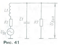
The transmission coefficient of the voltage increases, if R2 can be done large (for example, by connecting the circuit to the gate field-effect transistor serving to further amplify the signal). It remains to agree on the outline from the entrance (for example, with a 75-Ohm feeder antennas). Use the autotransformer connection (Fig. 39) or capacitive divider (Fig. 40).
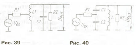
In the first case
R1 = R0(n1/n0)2,
where n1 is the number of turns from earth to drain: n0 - the total number of turns of the coil (the connection of the parts of the coil relies strong) In the second case
R1 = R0C12/(C1 +C2)2.
If R2 is not infinite, then you first need to consider it, calculating new R0 (reduced by the parallel connection of R2), and then count matched input. The parameters of the narrowband bandpass filter can significantly improve, including two, three, or more contours. The connection between them can to be inductive or capacitive. The coefficient of mutual induction is selected Q times smaller than the inductance of the coils and the capacitance of communication - the Q times less contoured containers, and Q is determined from the required bandwidth filter. If much less constructive quality factor of coils, the loss in filter out small. The input and output of the filter is loaded by a resistor R = PQ.
The signal in the circuit can be submitted not only in a parallel fashion, as described above, but sequentially, as in Fig. 41. Thus, if you want to get sharp the resonance curve, the resistance R2, as before, may have to choose more, a R1, on the contrary, perhaps less. With a small internal resistance generator this circuit has a large transmission coefficient of the voltage at the resonant frequency, in the limit equal to Q. the lowest frequencies ratio transmission tends not to zero, as already discussed in the filters, and to unity.
A very interesting case in the filter according to the scheme of Fig. 41 resistance at the input and outlet to choose equal characteristic, i.e., R1 = R2 = R.
It turns out coherent low-pass filter, the transfer coefficient is constant and equal to 1/2 (-6 dB) at all frequencies from zero to the resonant frequency of the circuit L1C1 and further increasing the frequency decreases. The steepness of the slope of the AFR is 12 dB per octave as it should be in the filter of the second order.
In the filter bandwidth 0…f0, the transmission coefficient is often assumed equal the unit, considering the input voltage of the EMF of the generator, and the voltage between upper circuit on the output resistor R1 and the common wire. Moreover, the resistor R1 may be the internal resistance of the generator. Generator like "sees" the load resistance R2 through the transparent bandwidth filter and gives maximum power at R1 = R2.
Incidentally, most gauges generators have a standard the internal resistance of 50 Ohms, and the scale of the output voltage is scaled to case their load by 50 Ohms. If the output of such a generator does not load, the output voltage will be twice more than the scale shows output attenuator!
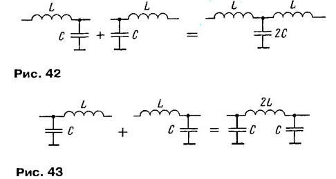
For more steep slopes AFC used a couple of the described l-shaped links, connecting them in accordance with Fig. 42, to form a T-shaped the link, or in accordance with Fig. 43 to form a U-shaped link. In this case get the low-pass filter of the third order. Usually prefer the U-shaped links, because they are less time-consuming to manufacture inductors.
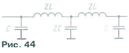
Perhaps further "extension" of the order of the filters, For example in Fig. 44 shows how two U-shaped units composed of two-tier fifth LPF order.
It has extremely steep frequency response in the stopband is 30 dB per octave. It is possible to make it even cooler if in parallel with the coils to connect additional capacitors of small capacity. At frequencies of resonant circuits formed get two points, "endless decay" lying in the stopband. In some cases, the role of additional capacitors can perform the stray the capacity of the coils.
HPF designs likewise, only coils are replaced by capacitors, and capacitors - coils. Broadband bandpass filters get cascade the connection of the LPF and HPF, preferably with a dual gain stage between them.
Question for self-examination. Using the formulas of this Chapter, print design equations for the inductance and capacitance of the l-shaped link of the LPF. Calculate the LPF in Fig. 44 for Amateur radio heterodyne receiver. Set the filter's cutoff frequency 2,7 kHz and the characteristic impedance of 1.6 ohms.
Draw a diagram of the filter with signs of the values of elements and build its frequency response on a logarithmic scale.
Response. The parameters of the agreed G-shaped link of the LPF (Fig. 41, 42) are from the ratio R = R, where R is the load impedance of the filter; R - its characteristic impedance equal to the reactive impedance of him elements at the cutoff frequency:
L=R/2πf c=1/2πf cR.After you have this formula already, it is easy to calculate the elements two-link LPF (Fig. 44) heterodyne receiver considering the fact that the inductance of both coils should be 2L, extreme capacity of capacitors With the capacity of the secondary condenser - 2C:
L= 1,6-103/6,28.2,7-103 - 0,095 H = 95 mH, 2L= 190 mH;With= 1/6,28·2,7·103·1,6·103 = 0,h-F = 0,037 UF, 2C = to 0.074 UF.
In the practical manufacture of the filter, the number of turns of the coil count, using the information outlined in Chapter 5. In this case it is advisable use a ferrite ring, providing a good quality factor of the coil and little susceptible to interference from extraneous fields. Worse in fact, and in another way the magnetic cores made of W-shaped steel plates, for example, from transformers used in portable transistor radios.
For example, calculate the number of turns of the coil on a ferrite ring from Khh ferrite brand 2000NM. We use the formula L=μμ0N2/l. Substituting the values μ = 2000, μ0 = 4π-10-7rH/M,S=16·10-6M2, l=38·10-3M, we have L-10-6N2 or N - 103L Substituting the value of L = 0,19 GN, we obtain N = 430 turns. It should be noted that, contrary to popular belief, such simple filters pretty not critical to the spread of the parameters of their elements, in any case of deviation ± 5 % very little impact on the shape of the frequency response. With appropriate precision permissible and calculations. Resistance of the source and load filter yet less critical, and here the permissible deviations of up to ± 25 %.
Author: V. Polyakov, Moscow