


")

The journal "Radio" in 2003, he published an article [1] about how using computer programs BPF-PP to calculate microwave stripline filter. Hams, which brought her into your album design software, you can Supplement it the proposed unit, which in conjunction with the BPF program PP will not only to determine the physical dimensions of the structure elements of the notch filter, but to analyze the frequency dependence of the coefficients of transmission and reflection.
For better readability of the results of calculation they are displayed on the monitor screen in the form graphs, which is easy to assess what changes need to be made in the source information. The results obtained with the help of this program, to allow more manufacture filter, best to choose the material for microstrip design, as well as the right "fit" it to the device for which it designed.
The first thing you need to do in order for the program to work, is to enter in the initial block BPF-PP line number 495, which will complement the information about the material of the workpiece. It looks like this:
495 INPUT "the loss Tangent of the dielectric substrate tg*e ="; TGD:TGD=TGD/10000.
Additional unit for calculating the characteristics of the filter incorporated information about the copper foil that for the majority of cases is enough, but when we can make changes. Usually in reference literature given the value of the loss tangent, for convenience inflated 10,000 times, and that takes into account line 495.
Then "sew" the program BPF-PP and additional software module on line 830 in a single unit. It is desirable to change the name of the "tailor-made" program, for example, BPF-PPGR, in which the letters GR let me remind you that she will submit and graphic material.
Now as an example let's perform the calculations for two different filter foil materials.
Enter the filter parameters (decimal comma, as is customary, replaced points):
Filter order <2-9>? 4
The type of filter? T
The load resistance RN (Ω)? 50
Border bandwidth, GHz:
Top ? 2.8
Lower ? 2.4
Next, the program highlights on the screen center frequency bandwidth: F0 = 2.592296 GHz.
The first option is made on the basis foiled fiberglass with a filler of epoxy resin:
Foil thickness, t, mm ? 0.05
The thickness of the substrate h, mm ?
The dielectric constant (E? 4.8
The loss tangent of the dielectric substrate tg*e4=? 250
The program performs the calculation of the fifty frequencies lying inside bandwidth, and at twenty-five values at each frequency ramp characteristics that offers to view the message on the screen:
View graphs: KN - enter '1'; km(log)-'2'; GVH-'Z'.
Graph KN displays the frequency response of the transmission coefficient for voltage. His appearance coincides with what we are used to seeing on the screen curve tracer when using the detector head with linear characteristic. Graph km is a logarithmic dependence of the coefficient the transmission power of the frequency. And the latest schedule - GVH - displays the coefficient the reflection power from the input of the filter. This image (like the envelope) observe, if you connect the filter to the generator frequency sweep (sweep) through the reflectometer.
If the program blocks "cross-linked" correctly, the screen will display graphics it is shown in Fig. 1-3. They represent the results of calculation according to the first embodiment is for fiberglass.
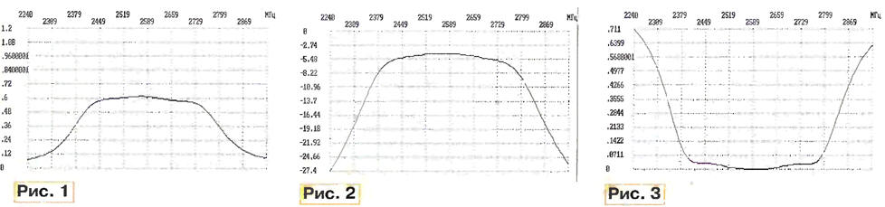
(click to enlarge)
For the second version of the filter on the material of FLAN - type:
Foil thickness t, mm ? 0.05
The thickness of the substrate h mm ? 2
The dielectric constant (E? 3.8
The loss tangent of the dielectric substrate tg*e4=? 12
In the result of calculations we get three more chart - Fig. 4-6.
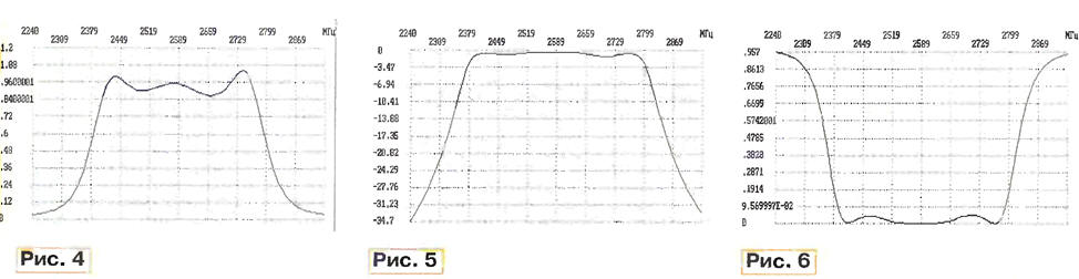
A comparison of the corresponding graphs of the two variants clearly shows that the use of foil fiberglass epoxy resin lead bad results on this frequency plot. At a higher frequency and smaller bandwidth settings will be even worse. Great fading signal due to the low quality factor of the resonators of the filter is less than 40 (Q<1/tg6), which build filter with satisfactory characteristics this material is a major effort.
The proposed program gives you the minimum you need to create a filter Microwave. Those who wish to improve, you can offer to create a block, providing for changes in the parameters of the inverters JY(k,k+1), for example, changes in the values of the coefficients A(K) And(K+1), etc. for the purpose more suitable.
You should not extend the frequency bandwidth of the analysis filter characteristics, as equivalent model true only in a passband and a small the adjacent areas. You should also not use this program for frequency more than 5…6 GHz, since the width of the microstrip resonators becomes commensurate with the length and increase the error due to the edge effect, which here taken into account the simplest way.
"Stitched" BPF program-PPGR
Literature
Author: O. Soldatov, Tashkent, Uzbekistan