


")

Consider a frequency-selective or selective circuits which have filter effect, i.e., the signals with the frequencies flow better with other worse. Sometimes such property chains is harmful, for example, in high-quality audio-frequency amplifier, where seek the widest possible bandwidth. While sometimes useful, say, in radios, when from the mass of signals of radio stations operating on different frequencies, it is necessary to distinguish the signal of a single broadcasting in known to you frequency.
Filter circuits (filters) are to contain reactive elements - the capacitance and/or inductance, since the resistance of the resistors from frequency does not depend (in the ideal case). In reality, there are always parasitic capacitance and inductance (installation, conclusions, p-n junctions, etc.), so almost every chain is in one degree or another filter, i.e. its the parameters depend on the frequency. First, consider the simple RC-circuit.
In Fig. 28,and shows a diagram of a simple low pass filter (LPF), permeable and debilitating low high frequency.
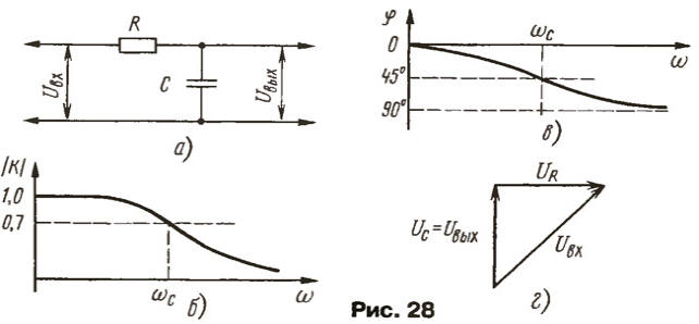
Transmission coefficient is the ratio K = Uвых/Uвх (more precisely, the modulus, or absolute value transfer coefficient). We calculate it using the known information already about AC circuits. The current in the circuit is:
and the output voltage equal to the voltage drop across the capacitor:

Substituting the current, we find
The transmission coefficient turned out to be complex. This means that the output the voltage of the filter is shifted in phase relative to the input. To emphasize the comprehensive nature of It, it is often referred to as K(jω). Find the module (absolute value) and argument (phase) To

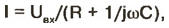
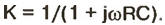
And the module and phase of the transmission coefficient is independent of frequency, or, as they say, are functions of frequency. The negative sign of the argument indicates the lag phase of the output signal from the phase input. If you build them schedules, get the amplitude-frequency and phase-frequency characteristics of the filter(frequency and phase response), it is shown in Fig. 28,6 and b respectively.
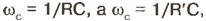
Applies the filter as follows. At the lowest frequencies capacitive the resistance of the capacitor is large and the signal is transmitted without attenuation from input to output through a resistance R. the Room to be re increasing the frequency capacitive the resistance drops and the chain works as a voltage divider. Frequency slice ωс capacitive resistance is active, a ωcRC = 1. However, the module not To equal to 1/2, as would be the case of resistances, and is 1/V2 = 0,7, as can be seen from the vector diagram of voltages (Fig. 28,g). Phase shift, insertion the chain at the cutoff frequency is 45° - so the phase of the output signal lags behind the phase of the input. With further increase in frequency module the transmission coefficient decreases proportionally to the frequency, and the phase shift tends to -90°.
Often to simplify calculations introduce the notation RC = τ. (time constant chain), ωRC = ω/ωс = x (generalized frequency). The transmission coefficient in these the notation is written quite simply:

To return to the previous notation it is useful only after completion of all calculations.
In our analysis, we tacitly assumed that the chain is powered by a generator with very low internal resistance, and its output does not loaded. In actually the signal source always has some internal the resistance R1, and if it is active, it should just be added to R. Similarly, if the load has a capacity of SN, it should just be added to S. If the load has a resistance RH, the module To already at their lowest frequencies, where the influence of the capacitance can be neglected, will be less than unity and will be (just believe in the law of Ohm) RH/(R + RH). The cutoff frequency also moves above and will be as easy to count as described above, is not
where R' is the resistance obtained by parallel connection of R and rn.
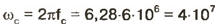
Here is an example of practical application of the presented information. Amplifier the TV must propheet bandwidth of 6 MHz, and it works on capacitive the load, consisting of the output capacitance of the transistor St, the capacitance Cm and installation interelectrode capacitance of the control grid of the kinescope SC (Fig. 29,a). Their sum you can evaluate any capacity gauge (of course, if disabled TV!) or on the reference data. She was 25 PF - this will be the capacity of the considered RC-chain. The resistance R of the chain is obtained by parallel connection of the internal resistance of the transistor (generator signal) and the load resistance RL. The first can be found at collector the characteristics of the transistor, taking a small increment ΔUк close working the collector voltage IR and finding the corresponding increment of the current ΔIк
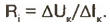
Usually, the internal resistance is much more of the load resistance, then we can assume R = RL.
Find the allowable load resistance based on the dam response to 0.7 (3 dB) at a frequency of 6 MHz. The angular cutoff frequency will be
(rounded). As RC = 1 /ωс,

Naturally, we would like to choose the load resistance more that will increase the gain and reduce power consumed by the transistor current, but to do this not because of a blockage of the upper frequencies of videospicture that will lead to the loss picture clarity.
For the sake of interest we will continue the calculation. Let on the grid of the kinescope must give the signal the amplitude to 50, then the current of the transistor needs to be 50 mA. On the load resistance will drop also 50 V, the supply voltage must to be not less than 100 V and the load resistor will be allocated a capacity of 50 In - 50 mA = 2.5 watts. The same power will be dissipated on the transistor. Load characteristic for this case is shown in Fig. 29,b together with plots voltage and current (which in television, it should be noted, rarely sinusoidal). Now it should be clear why the output stage of the amplifier perform high-power transistor and the load put powerful resistor, though no power on the circuit control electrode (grid) kinescope does not consume.
In order to improve the situation, invented a lot of ways. One of them is correction of AFC inclusion in series with the load coil with a small inductance (Fig. 29,a), chosen so that it resonated with total a container somewhere on the cutoff frequency or higher. Formed resonant circuit with a very low quality factor (1…1.5) contributes the rise of the frequency response near the cutoff frequency. In Fig. 29,the solid line shows the frequency response amplifier before correction corresponding to the frequency response of a simple RC-circuit, and bar - after switching inductance. In this way widen the band for the transmission frequencies of 1.5…2 times, or as many times increase the gain and efficiency cascade.
Describes the narrowing of the bandwidth of above amplification occurs in each the cascade that need to be considered when designing multistage amplifiers. For example, in the case of two identical cascades dam AFC in each should not be more 0,84(0,842 = 0,7), in the case of three - no more than 0,89. Sometimes, especially in amplifiers, use tricks of the trade: a preliminary stage, in which and interelectrode capacitance, and output voltage swing less design of broadband, with the rise of frequency response at higher frequencies, compensating blockage of ripple in the output stage.
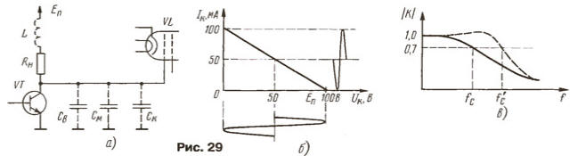
Described the chain (see Fig. 28,a) is called a low-pass filter, when you gaze at it frequency characteristics, and it is also called an integrator when considering the passage of the pulse signal. Let the input of the chain has a drop voltage with short front (Fig. 30). The output voltage will not increase immediately, because the capacitor needs time to charge current, limited resistor R.
Only in the rst time point after exposure to the differential current will be equal UBX/R, then it will decrease with increasing voltage on the capacitor. Accounting for the differential equation for the voltage at the output and decided it is possible to establish that
where e is the base of natural logarithms. At time τ = RC the output voltage grows to about 0.63 and from the input and then asymptotically approaches him. Thus, integrating the supply chain "floods" cool the fronts of the signal, which, incidentally, accounts for the reduction-definition television image.
Let's move to the highpass filters (HPF), the simplest of which (differentiating RC-chain) is shown in Fig. 31 ,and. The transmission coefficient is now is expressed as:

The frequency response of the chain shown in Fig. 31 ,b. The formula for the cutoff frequency remains the same. The phase response is unchanged, but f changes sign, the phase of the output signal is ahead of the phase input. It is close to 90° at low frequencies and approaches zero at high (see graph Fig. 28,it is enough to move up along the axis φ 90°). In fact, all expressions for HPF are obtained from the formulas for the LPF when replacing generalized frequency x-1/x', which is very often and used in the calculation of any filters.
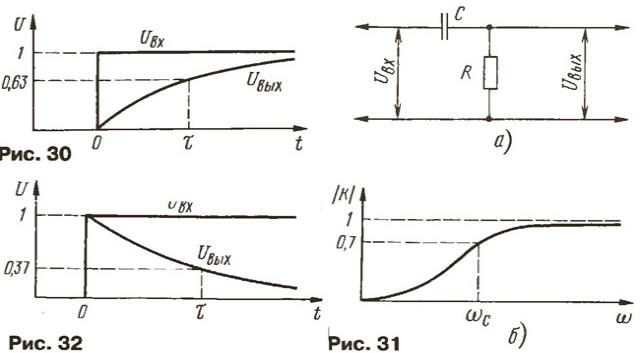
Impulse response of the chain shown in Fig. 32. She would return previous - the output voltage increases abruptly, but then falls on the exponential law in accordance with vilaines a time equal to a constant time chain t, it decreases to 0.37 input for the next interval t - again to 0.37, and so on (by the way, this is a good rule to draw the Exhibitor per division horizontal vertical coordinate of the curve must increase or decrease by the same percentage).
Almost every interstage separation of the RC-chain is a described HPF. Even if the resistance R in an explicit form is missing, it is the input impedance of the cascade included for dividing capacitor. If we consider that the parasitic capacitance at the output of the cascade forms a high-pass filter, it becomes it is clear that any amplifying cascade limits the bandwidth skip frequency as from below and from above, i.e. it is a bandpass filter. The rectangular-shaped pulses passing through the amplifying cascade, flatten steep fronts (LPF) and collapses the top (HPF).
To increase the filtering action of RC-circuits include several of them, one after the other, and to exclude bypass grafting chains next, divide them by the intermediate amplifier stage transistors. Sometimes for the same purpose subsequent chain chosen with great resistance. But in any case, the frequency response of filters in the region of the cutoff frequency very gentle.
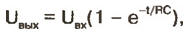
To rectify the situation allow active filters, where the amplifying element (transistor) serves as a filter element. In Fig. 33 shows a diagram of the active LPF (Sallen-Ki). The active element in it must have unity gain and not to invert the signal. Additionally requires high input and low output resistance. Those requirements can be met smithery (source) follower transistor or (better) operational amplifier, the inverting input of which connected to the output. Resistors are usually chosen with the same resistance, and the capacitance of the capacitor C2 in 2…2.5 times less than the capacitance C1. The cutoff frequency filter
The filter acts. At frequencies below the cutoff frequency of the RC-chain output the voltage almost identical to the input and the capacitor C1 is off from work because both plates have the same potential. The signal is transmitted without the weakening. With increasing frequency comes into effect circuit RC2 and output the voltage decreases. Then in effect and circuit RC1, and more attenuating the output signal. The result is a steep decline in frequency response above the frequency slice.
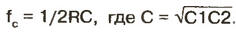
By changing the ratio of capacitances C1 and C2, one can obtain a smooth and monotonically the falling frequency response within the passband (Butterworth filter), and you can even to form a slight recovery before the cut-off frequency (Chebyshev filter).
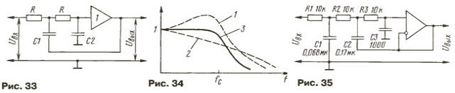
Forming such a rise (curve 1 in Fig. 34), it is advisable to add another passive link (curve 2), which compensates for the rise and will make the slope of the frequency response for the cut-off frequency even cooler (curve 3) is a |K| a will decrease 8 times in two-fold increase in the frequency. Get the filter for the third-order slope slope of 18 dB per octave. As an example in Fig. 35 shows a diagram of such a LPF with the cut-off frequency of 3 kHz. At other frequencies the filter is easy to rebuild, changing the values of all capacitances is proportional to the frequency. HPF with similar characteristics it turns out, if you swap the resistors and capacitors and alter their values.
Oh okay filters: it is determined by the number of reactive elements of the filter, and from the order depends on the steepness of the slope of the frequency response. Thus, the links of the first order (Fig. 28,and 31, (a) give the attenuation at 2 times the second time the frequency change (6 dB/Oct.), the second order filter (Fig. 33) - 4 times (12 dB/Oct.), filter the third order (Fig. 35) - 8 (18 dB/Oct.).
Question for self-examination. Some high quality (bandwidth 20 Hz…20 kHz) amplifier 3H has an input impedance of 100 ohms, the signal source is the same the output impedance. They are connected by a shielded cable with linear capacity 100 pF/m cable Length - 3.2 m. in addition, the input of the amplifier included the dividing capacitor of 0.01 UF. Properly done, what is will actually be a band and how to act to correct the situation?
Response. Draw the equivalent circuit (Fig. 63) containing the source signal G1 with internal resistance g, cable with capacitance C1, the separation the capacitor C2 and the input impedance of the amplifier is R1.
The upper frequencies are attenuated by the capacitance of the cable, which is connected in parallel the input resistance R1 and the internal resistance of the source signal r. The coupling capacitor C2 at high frequencies is negligible resistance and can be ignored. Parallel connection of two resistance of 100 kω gives a value of 50 ohms. The cable capacitance C1 is 100 pF/m x 3.2 m = 320 pF. According to the formula f c= 1/2πRC defined top frequent bandwidth:
f B= 1/6,28·320·10-12-50·103 = 104 Hz = 10 kHz.
To increase it up to 20 kHz or twice as necessary to shorten the cable, or cable select with half as much heat input capacity, or to decrease to approximately 30 ohms output the source impedance of that calculation, that the total impedance, connected in parallel to the cable, amounted to from 50 to 25 ohms.
The latter method is preferable since it increases the voltage on the input of the amplifier. Indeed, in case of equality of the resistances of the source and amplifier it is half the EMF source, and if you lower the resistance source up to 30 ohms it reaches 75% of the source EMF.
For this reason, often the output of signal sources, working on long connecting cables, install the cathode, emitter, or source follower with low output impedance.
Let us calculate now the lower edge frequency of the bandwidth. It is defined the dividing capacitor C2 (0.01 UF) and a total resistance of series-connected signal source and the amplifier input (r+R1 = 100+100 = 200 kω). By the same formula calculated the cutoff frequency of this RC-circuit (HPF): fH = 1/2πRC= 1/6,28·2·105·10-8 = 80 Hz. To lower the cutoff frequency to 20 Hz capacity a coupling capacitor must be increased at least 4 times. Nearest standard value of the capacitance - 0,047 UF.
If in accordance with the above recommendation output the impedance of the signal source g will be reduced to 30 ohms, then the total the resistance of the chain HPF are r + R1 = 30 + 100 = 130 ohms, and the required the capacity of the coupling capacitor will be equal to:
C = 1/2πf HR= 1/6,28·20·1,3-105= 0,07 UF.
Author: V. Polyakov, Moscow