


")

The author of the article talks about some of the aspects of building multi-tier frequency RC filters and select items for them.
As you know, a low pass filter (LPF), whose scheme is depicted in Fig. 1 and, conceded in nafasku signals from DC to the cutoff frequency (band transmission) and attenuates signals of higher frequencies (band attenuation). For the cutoff frequency f0 (Fig. 1 ,b) accept that at which the curve the amplitude-frequency characteristic (AFC) of the filter is reduced by 3 dB (more precisely in √2). This level is chosen because this is when the voltage the input power is P=U2/r is reduced by 2 times.
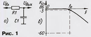
The cutoff frequency of the single-link (1st order RC-filter is equal to f0=1/2πτ, where τ = RC. Its very AFC of the canopy, the in-band attenuation decay characteristics is only 6 dB at octave (frequency doubled) or 20 dB per decade (ten times).
To increase the steepness of the decline, you can apply multiple RC-links included consistently. In order for the links from affecting one another, they are divided buffer repeaters voltage, as shown in Fig. 2, and.
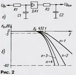
The two-link filter the AFC decay will be approximately 12 dB/Oct, three-tier - 18 dB/Oct, chetyrehzvennoj th - 24 dB/Oct, and so on (Fig. 2,b; the vertical axis represents the normalized transmission coefficient). In General frequency response of the multi-filter will be the product of its frequency response links, and the cutoff frequency is reduced to α = 1/√n√2-1, where n is the number of links.
In Fig. 2 b shows a decrease of the cutoff frequency f0 with increasing number of links filter. The table shows values for filters and the number of links from 2 to 10.
Such a filter can be easily performed on any amplifier with any coefficient gain (greater and less than unity), even with a different sign of the gain (i.e., by inverting or not). Just the total transmission coefficient voltage Key in the bandwidth will be equal to the product of the coefficients of all the links.
Another advantage of this filter is very "soft", without hesitation and emissions reaction to sudden level of the input signal.
If RC build links the filter does not lower and the upper frequencies (Fig. 3,a), the cutoff frequency for each level will not decrease and increase (Fig. 3, b), but the numerical value of the coefficient a remains the same.
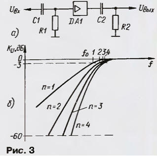
Such a change of the cutoff frequency must be considered when designing the device with several stages and a corresponding number of the dividing capacitors. If, for example, dividing the number of capacitors is equal to 10, and the lower frequency the cut must be equal to 20 Hz, then each low-pass filter formed by capacitor together with an input impedance of the next stage, should have a cutoff frequency around 5.4 Hz.
The same applies to the choice of correction capacitors OS-forming the characteristic of the LPF. If several such capacitors or RC-circuit between node device that limits the frequency band above, the cutoff frequency of each these should be selected above the upper operating frequency of the device in General.
Author: A. Branov, Penza