Improving the quality of reception УSW FM programs at small signal levels the task difficult. Very often for its decision applied the device is not less complex than receivers. The article offers a simple way to reduce the noise level when receiving signals from a remote radio station.
It is known that the adopted systems УSW-stereo broadcast, domestic - polar modulation (PM), and foreign - with pilot-tone (PT), frequency band integrated stereo signal (CSN) is much wider stripes transmission 3H. As a result the accompanying CSS "nationally" noise decoded along with the stereo and is in the audible region of the audio spectrum thus deteriorating the ratio signal/noise 10...18 dB compared to monaural mode.
In order to maintain acceptable sound quality, I have to translate stereodecoder in Mono already during the reception of signals at which original ratio signal/noise of monodrama drops to 40...48 dB. Available auto switch "Mono - Stereo" this problem does not solve, so as to be responsive only to the presence of podnesushchih KCC and not on the actual ratio signal/noise ratio.
To reduce noise stereopathetic radio Amateurs proposed multiple devices [1, 2], operating on the principle of parallel connection of the left and right output channels of the decoder with decreasing received signal to some level. This uses the fact that the noise components are in antiphase channels and when translated in mono mode they cancel each other out. Unfortunately, the quality of such noise in the whole dynamic range small, they can rather be considered as a threshold device that reduces the visibility of noise in the pauses, and noted in [1 ].
Offer a fundamentally different way to solve circuit solution which does not require energy (can be used in wearable equipment) and does not introduce additional non-linear distortion. It is based on dependence level noise and the degree of separation of the stereo channels from the nonlinearity of the amplitude-frequency response curve in nazionalnoi the frequency band from 20 to 50...70 kHz. So, a blockage in this area 6 dB per octave, obtained by using the simplest odnokon-tion the low-pass filter in the decoder on the chip CHA, dramatically reduces noise, but at the same time and degrades real channel separation with 34...43 dB to 24 dB for PM and 20 dB for PT [3]. True reverse - recovery response in this region contributes to a better separation stereo channels with reduced signal-to-noise ratio. In addition, the frequency correction KCC is also needed to compensate for losses in FM detector. In the receivers of the highest category of complexity is even recommended after to include prior USC providing recovery response at higher frequencies KCC [4].
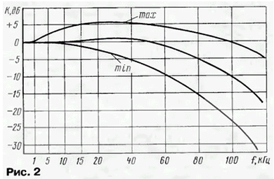
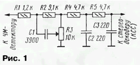
Thus, adjusting the AFR KCC before stereodecoder, you can get different the final quality of the signals 3H at the outputs from very good, with a maximum transient attenuation between channels - for strong stations, to satisfactory close to "Mono" for a remote. This principle is in the basis of the proposed device (Fig.1), consisting of an adjustable link R1R2R3C1 and unregulated LPF R4C2R5C3.
The work of the adjustable link depends on the position of the variable resistor R3. In the top circuit position (max) produces a rise in NATO-tional and partially, in the tone areas due to the action of HPF R2C1 (Fig. 2). As move the engine down the frequency of the twist increases, the rise in this region decreases and, in addition, begins to operate low-pass filter R1C1. In the lowermost the position of the slider of the resistor R3 (min) HPF deleted and active LPF provides necessary the AFC decay.

The second low-pass filter designed to suppress noise and out-of-band signals at the borders the frequency spectrum of the KCC. It helps to reduce interference and noise at the output of the decoder,and without the deterioration of the real quality of the separation of the stereo channels, as tonal KCC area is not affected.
As can be seen from the graphs Fig. 2, in the upper position gives rise approximately 5 dB in a wide frequency range 5...70 kHz. In the middle position the regulator's frequency response is almost linear up to 60 kHz, with a further decline in the boundaries of KCC. Finally, in the lower position appears to decline at frequencies above 19 kHz, debilitating nadtonalnyh part of the stereo signal.
The obtained characteristics are acceptable for stereodecoder as FRI, and with PM. In both cases, the necessary control range parameters of the output signal 3H of noise and transient attenuation between channels.
Due to the simplicity, the filter can be easily applied to any finished device - stereo or radio, except, perhaps, the most miniature. Of course, do not exclude its application in new developments, for example, dostanete stereodecoder.
In the author's version used the following details: variable resistor company TELPOD (similar to the SDR-4M), constant - MLT 0,125, capacitors - type km-4.
Variable resistor R3 (see Fig. 1) this device performs the functions soft switch "Mono - Stereo". Therefore, when improving your stereo receiver available step switch "Mono - Stereo" becomes unnecessary. It can be removed, switched them with the chain is fixed in position, corresponding to the "Stereo" mode. In place of the remote switch should set the variable resistor R3 with the matching handle design. Possible another option is to leave the existing switch in "Mono - Stereo", and smooth the regulator R3 to position next to him.

Embedding the filter is to dismantle the existing input circuit stereodecoder (except transient capacitors) and install in its place the elements of the proposed filter. Mounting hinged, arbitrary, the only requirement to it - to connect the hinged part of the circuit with a variable resistor R3 shielded wire to avoid interference.
The attenuation caused by the filter at a frequency of 1000 Hz, is the sum of the losses in the regulated level (5 dB) and reduce the signal divider formed by total the resistance of resistors R4, R5 and the input resistance of the chip stereodecoder. The latter can be different, which affects the overall rate transmission. Because of the special elements of tuning the filter does not contain (their the introduction would increase the attenuation to invalid), the following the method of matching with a specific type of chip.
To rework fed to the input of a standard circuit immediately after the FM detector a sinusoidal voltage of 50 mV (effective value) with a frequency of 1000 Hz and measure the output signal of any channel of stereodecoder after correcting the LPF. Then embed the filter, as described above, and when applying the same test signal at its input again check the output voltage at the same point. If it has changed significantly, we choose the values of resistors R4, R5, bringing the output level to the original value, and then proportionally change the capacitance of the capacitors C2 and C3 according to the condition of a constant constant time τ= R4C2=R5C3. Similar operation can be performed and the output of the LPF correction of the frequency pre-emphasis, saving them time constant of 50...70 μs. The method ensures that the volume of the intake after the filter will not change.
The author of the filter applied in the radio "SHARP GF-6363" with stereodecoder on chip VA. Subjectively, the quality of his work can be estimated as way. When receiving strong stations and installation of the regulator R3 in upper circuit the situation greatly improves the stereo effect and emphasizes the upper frequencies of the sound spectrum, as HPF R2C1 has been in place since 4 kHz, i.e. works as a tone control. In this case the audio was as clear (compared to the average position of the regulator), clearly localized tools created a great stereo panorama. The increase of noise depends on the source the quality of the received program and for the most powerful stations in the receive location - "Russian radio") is barely visible, even in the pauses. In the middle position of the regulator the sound corresponds to the usual "Stereo" mode with a somewhat reduced level noise. As we approach the engine to the bottom of the regulator according to the scheme position the stereo effect is getting worse, dulled treble, but at the same time reduced noise, allowing you to take in far mode station. In the end position, the sound almost mono, and for weak signals stereodecoder automatically switches to Mono, what says the failure indicator stereorama.
From the above it is clear that the proposed filter KCC is a very convenient and flexible body can be adjusted to obtain the adaptive quality signal in almost any conditions. The filter operates smoothly and all dynamic range, which distinguishes it from the stepped switches "Mono - Stereo" noise and threshold. It is not excluded further automation and sharing with the mentioned devices.
Literature
Author: Dmitry Pakhomov


