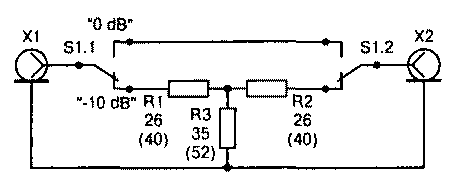
To avoid such "randomness", it is necessary to adopt a rule to enable the transmitter on the setting with a matching unit only through the attenuator. It can be incorporated in the matching unit and performed separately, as shown in the figure, of course, if the transmitter provides continuous adjustment of power.

To be able to produce long setting stattoo transmitter, the power dissipation of R1 and R2 should not be less than 25 watts, R3 -30 watts. They are drawn from the resistors MLT-2 to the value shown in the diagram (without the brackets for 50 Ohm tract, in brackets - to 75-Ohm). CWS TX-attenuator will be close to 1:1 for almost all real cases the error attenuator to the antenna, and idling and short-circuit protection - will not exceed 2:1, which is acceptable for transistor transmitters.
This attenuator can be used in any case as simple and "matching" device, for example, in case of emergency failure of the main antenna and the need to work on surrogate antenna, resigned, of course, with attenuation in 10 dB -10 times the power at a matched antenna. In the case of a mismatched antenna losses can be both more and less than 10 dB.
On HF bands, where most often there is a mismatch of random antennas and the failure of the transistors, even at QRP can carry out the necessary QSO's and be completely confident in the safety of the transmitter. Attenuation of 10 dB in the receive mode, as experience shows, in many cases it is possible to compensate "forces" of the transceiver, such as UHF.
In many cases there is no need to pump in RA all the power of the transceiver, and the declining capacity of its driver can increase the noise while transmitting. The attenuator will allow you to avoid this. It will be useful and for adjusting the antenna devices requiring low power, such as RF bridge, and in the measurement of radiation patterns.
Author: Igor Grigorov, RK3ZK, Belgorod; Publication: N. Bolshakov, rf.atnn.ru


