


")

The development of personal communications (pagers, cordless phones, etc.) has led to the emergence of Amateur radio interference from transmitting devices of these systems, which work at frequencies close to the frequencies of the Amateur bands. To eliminate this kind of interference can, by setting the receiver input УSW radio the bandpass filter. One of the options of this filter are described in the published article.
The antenna filter is designed to improve the selectivity of the receiving path УSW radio band 144 MHz. It is a high-q two-circuit bandpass filter centered selection with inductive coupling between the contours. To reduce power losses when operating radio station on УSW transmission filter disables high frequency VOX.
Made the author of the filter has the following characteristics:
- input and output impedance - 50 Ohms;
- bandwidth at 0 dB level non-uniformity of less than 0.2 dB to 2 MHz (144…146 MHz);
- the bandwidth of the level - 6 dB - 4 MHz (143 147…MHz);
- the bandwidth of the level - 20 dB to 6 MHz (142 148…MHz);
- insertion loss in the operating frequency band is not more than 1.5 dB.
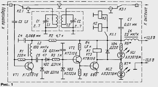
The filter circuit (L1C1L2C2) to the management node (VT1-VT3) is shown in Fig. 1. Node management is nothing special compared to similar devices, described in the literature, has not. LEDs HL1 and HL2 are set only when need to indicate modes "Bypass" and "Filter". Relay K1 with any type working voltage winding 10…12 V. the Selection mode of the transistor VT1 when setting device for making the VOX operation throughout the power range used radio (from minimum to maximum).
More detail on the design of the filter directly.
Its body (Fig. 2) made of double-sided foil fiberglass thickness 1.5 to 2.0 mm and is a rectangular a box with two compartments. The partition between the compartments of the filter (Fig. 3) - from foiled on one side of the fiberglass thickness: 1.0 to 1.5 mm. Two holes with a diameter of 8 mm are designed for installation of trimmer capacitors. The elements of the body are interconnected by soldering. Before assembling the parts of the case it is advisable to clean fine sandpaper from traces of oxidation and other damage, and then Polish with the foil, it is desirable to Shine.
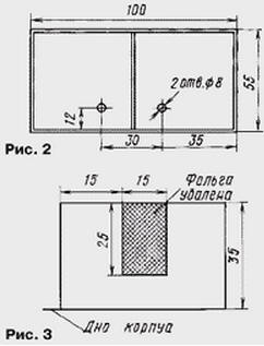
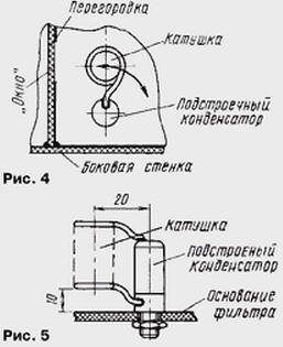
Inductive coupling between the circuits is performed through the "window" size 25x15 mm in the partition. The location of the "window" on the partition relative to the coils of the filter it is shown in Fig. 4.
To ensure the required characteristics of the filter and getting the most possible figure of merit of a circuit made from two millimeter silvered copper wire.
These coils: the number of turns is 6, the diameter of 13.4 mm, the winding length of 15 mm. The approximate inductance - 0,31 mH. The outlets of the coils for connection with an antenna and the radio station made from "cold" end and are selected when fitting the input and output impedances. In the author's copy of the withdrawal made from 0.5 revolution.
Coils are soldered directly to the trimmer capacitors type ctpc (Fig. 5) and when you configure the filter, turning with the capacitors (see Fig. 4), can get close to the "window" in the partition or to move away from it. Thus adjustable inductive coupling between the circuits. On top of the filter lid, made of tin-plated copper (brass) foil.
Switching of the filter is high frequency relays K1 and K2 type on CD the operating voltage of 13 V. Conclusions from the coils L1 and L2, the connection between the contacts relays, and connections to external devices are made of 50 Ohm coaxial cable.
Filter setup was performed using the instrument for the study amplitude-frequency characteristics of the H1-48 and antenna analyzer MFJ-259.
Customized filter together with relay and RF channels is placed in a metal VOX the housing, which is common to the entire device screen. Powered device from the power supply УSW radio station.
The author expresses appreciation to UA3AAX and RA3ACC for valuable tips and advice when manufacturing and developing filter.
Author: Vladimir Gordienko (RU3BE)