Fig. 1
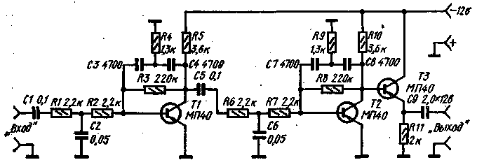
The frequency response of the first stage is formed by the feedback circuit R4C3C4. Phase relationships in the circuit are such that at frequencies of 2-3 kHz is obtained a lifting of the gain and at frequencies above 3 kHz the gain drops sharply due to strong negative feedback. At low frequencies the capacitive reactance of the capacitors C3 and C4 is high and the feedback is almost absent. Passive T-shaped link R1R2C2 compensates the rise of the gain and causes even greater attenuation of frequencies above 3 kHz. The resistor R3 generates the offset and stabilizes the cascade mode. The second cascade is assembled in a similar way. The emitter follower eliminates the effect of the load on the filter settings. If the filter works on vysokogornogo load (more than 5 ohms), then the emitter follower can be excluded, and the output signal to remove from the collector of T2.
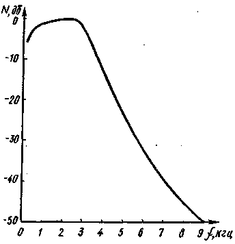
Normalized frequency response of the device shown in Fig. 2. To avoid nonlinear distortion of the input signal should not exceed 10 mV. The amplitude of the signal reaches 2 V, that is sufficient for the direct filing, for example, on semiconductor balanced modulator.

Fig. 2
The filter is relatively non-critical to the argument of the included resistors and capacitors, so it is possible to use parts with a tolerance of +-10%. Is indicated in the diagram, you can use any low-frequency transistors with TSA=50-100. If done correctly mounting the establishment of a filter is not required.
Shown in the diagram denominations get the flattest frequency response in the band of 300 Hz - 3 kHz. Decrease or increase the capacitance of the capacitors C2 and C6 creates correspondingly rise or fall characteristics at frequencies of 2-3 kHz. If to improve speech intelligibility, it is desirable to obtain a smooth decay characteristics in the low frequency region, it is necessary to reduce the capacity of transitional capacitors C1 and C5. The gain of the signal thus somewhat reduced.
If the signal at the input of the filter is fed from the output of the transistor amplifier circuit, the resistor R1 should be deleted and the resistance of the resistor in the collector circuit of this transistor to select equal to 2.2 kω.
Author: V. Polyakov (RA3AAE); Publication: N. Bolshakov, rf.atnn.ru


