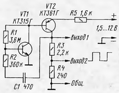
To test and develop different amplifiers, including amplifiers 3H, it is useful to use the generator of rectangular pulses. Usually such generators carry out under the scheme of the symmetric multivibrator on two bipolar transistors of the same structure and with two customizability chains. However you can gather more than a simple generator with two transistors of different structure (see figure) with one castorocauda chain.

Generator works. When applying the supply voltage (the capacitor C1 is not charged), the transistor VT1 is opened and the current flowing through the resistor bias R1. The collector current of this transistor is the base of VT2 and opens it. Increasing the voltage on the collector load through the last chain C1R2 more opens the transistor VT1, the result is avalanche process opening of both transistors is formed in the front rectangular pulse.
The duration of the pulse peak is determined by the charging time the capacitor C1 through the resistor R2. As the charging of this capacitor current base transistor VT1 decreases and there comes a time when an avalanche occurs the closing process of both transistors. The load was negative the voltage drop is the decline of the pulse. The duration of the pause between pulses is determined by the duration of discharge of capacitor C1 by the current flowing through resistors R1 and R2. Then the process repeats.
The operation of the generator can be explained otherwise. Two-stage amplifier covered chain positive feedback (R2C1) and at the same time, displayed on a linear mode transistor VT1 serving bias on its base through the resistor R1. So relaxation oscillations occur. To stabilize the operation of each generator cascade covered chain FOS in the first stage it is small and is carried out through the resistor R1 and the second cascade in the emitter circuit of the transistor VT2 is included the resistor R5.
The generator is stable at the power voltage from 1.5 to 12 V, while current consumption is 0.15 to units of milliamps. The amplitude of the output pulses "Output 1" is slightly higher than half of the supply voltage, and "Output 2" it is about 10 times less. If you want you can make another one the degree of division (1 /100), adding between the bottom under the scheme the output resistor R4 and common wire resistor 240m.
When specified on the diagram the values of parts and at a voltage of 2.5 V supply current was 0.2 mA, pulse frequency is 1000 Hz,duty cycle - 2(square wave), the amplitude of the pulses at the "Exit 1" - 1B.
Of course, that such a simple generator signal parameters depend markedly from the voltage of the power source. So adjust the generator should though the voltage at which it will be used. In the absence of the generation choose the resistor R1 and, possibly, R5. Duty cycle set the selection of resistor R2.
One of the possible applications of the generator as a flashing light beacon, for example, the guard device. Then in series with the resistor R5 include a light-emitting diode or a miniature incandescent lamp, and the capacitor is used capacity to fractions of a microfarad, so that the generation frequency was 0.5...1 Hz. For obtain the necessary brightness of the indicator light can be set resistors R3, R5 of least resistance, and R4 be deleted as unnecessary.
Author: V. Polyakov, Moscow


