


")

My work "laboratory" power supply has served for more than 20 years. Repeatedly repairing it after extreme stress, I came to the conclusion that the necessary adjustable overcurrent protection. 5 years ago I designed a circuit power supply on a chip CES, and since then forgot about it repaired. The proposed scheme of the power supply unit (PSU) can serve as a laboratory source of voltage adjustment range voltage 3…30 V and a charging device for the adjustment of the charging current of the battery (AB).
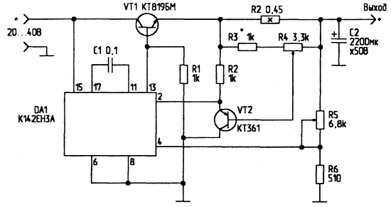
Fig. 1. Schematic diagram of the PSU
Chip CSA is an adjustable voltage regulator with protection from overcurrent and allows to obtain an output voltage from 3 to 30 V At a load current up to 1 A. additional amplifier power transistor VT1 and adjustable current protection scheme, will receive a universal reliable PSU.
Transistor VT1 is the "amoxycillin" of the output transistor circuits and provides output current up to 15 A at dissipated in it the power to 100 watts. For this purpose it is mounted on the radiator area of at least 200 cm2 with good ventilation. Desirable forced air cooling fan.
Circuit control voltage operates as follows. When the current flows through the resistor R2, the voltage drop across the voltage divider R3-R4 and the emitter follower VT2 affects the input protection circuit DA1. Resistor R3 limits the maximum current protection operation. Slimming R3, increase the maximum value of current at which protection is triggered. Resistor R4 sets the limit tripping.
If BP is to be used as laboratory, input voltage, it is desirable to choose about 40 V. the output of the PSU adjustment range voltage ranges from 3 to 30 V. it is Necessary to consider that at high load currents and low output voltage of transistor VT1 will dissipate power equal to:
PP = (Uвх - Uвых) I N (W)
So, if you don't need high output voltage, input voltage, it is desirable to reduce to 20…25 V.
The output voltage is monitored by a voltmeter. To control the current, you can turn on the ammeter. The resistor R4 is to equip the scale is calibrated from the minimum pickup current protection (I - 20 mA) to the maximum. As R4 is possible to use multi-turn, or a resistor with a Vernier device.
When charging the battery the procedure works like this:
engines resistors R4 and R5 are set to minimum;
- AB is connected according to the polarity;
- the power is turned on;
- voltage regulator (R5) is set to the maximum value. However, the current is absent;
- current controller (R4) gradually increases the current to the desired value;
- voltage regulator output to a minimum, until the current starts to decline;
- voltage regulator finally install the desired charging current.
If this PSU to supply with timer, disable it through the time required for charging the battery, you get automatic charger.
Author: K. Selyugin, Novorossiysk; Publication: www.cxem.net