In the operation of laboratory power supplies often there is a need monitor the current consumed by the load. In most cases, with this purpose in the output circuit block is administered low-impedance resistor (current sensor), and parallel to it connect pointer instrument (Milli - or microammeter). For full deflection his hands are often required to 0.3...0.5 V, so the sensor must not fall lower voltage. If there is a ham radio operator there is a dial the device, more challenging, this option controls unacceptable First, because the current sensor will fall noticeable part of the output voltage, and secondly, due to the significant allocation of heat on it at currents more than 1...2 A.
A possible solution in this case is described below the device allows to reduce the resistance of the current sensor to an acceptable values. In addition, this device is easy to implement or light the audio alarm of exceeded the output current of a predetermined value.
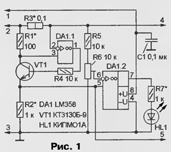
Schematic diagram of the device shown in Fig. 1.

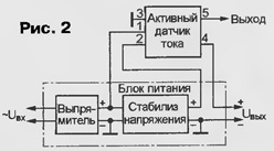
As you can see, it performed on dual OS LM358, able to operate on single supply, and the transistor VT1. On one of the OS (DA1.1) and the assembled transistor current Converter, on the other (DA1.2) comparator. The device includes in the output circuit of the power supply unit in accordance with Fig. 2. In this case, the output power of the shelter DA1.1 receives voltage, exceeding the voltage at its inputs, which results in normal mode work.

The Converter operates as follows. When the flow of the output current on the resistor R3 is a current sensor generates a voltage drop. As a result the output of op-amp DA1.1 there is a voltage that opens the transistor VT1, and through resistors R1 and R2 current begins to flow. Its value is set to what is the voltage drop across the resistors R1 and R3 are equal. In other words, through the transistor flows a current of approximately R1/R3 = 1000 times smaller than the output the current power supply IOUT. For example, if the latter is equal to 1 And, via a resistor R2 flows a current of 1 mA. The resistance of this resistor is 1 kω, the fall voltage UR2 in this case is 1, i.e. the conversion factor current/voltage equal to 1. In the General case, UR2 = IOUT (R3/R1)R2. The nominals resistors can be implemented in various conversion factors.
The output voltage UR2 is supplied to the non-inverting input of op-amp DA1.2, and the inverting exemplary voltage is supplied iobr with engine trim resistor R6. If UR2 not exceed iobr, DA1 output of op-amp.2 supported the voltage is close to zero, and HL1 led is not lit. When UR2 exceeds iobr, the voltage at the output of op-amp becomes equal to the supply voltage and the led will begin to glow, signaling that the output current has exceeded the set value.
The device is designed to work with power supplies in which the voltage the output of the rectifier is in the range from 5 to 32 V.
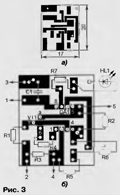
In the presence of the transistor CTB-9, small parts for surface installation (for example, capacitor K10-17B, resistors R1-12 or similar foreign production and trimmer type POZ3AN RVG3A, RVG4A) the device is mounted on a printed circuit Board of bilateral folgering fiberglass, made in accordance with Fig. 3,and (foil second side used as a General guide). The placement of parts on the motherboard shown in Fig. 3,b. The traces connect different sides of the wire lintels over openings.

If you apply the transistor series KT3102 (with index A, b or E), constant resistors MLT, C2-33, trimming SDR-19 and capacitor K10-17A, Board size will have to increase accordingly. The resistor R3 can be made from a piece high resistance (e.g. wire) wire. Led HL1 - with any operating current up to 25 mA.
Establishing device is reduced to the selection of resistors R1-R3 to obtain the desired conversion factor. The value and power of the resistor R7 is chosen based on the desired current through the led when the voltage at the output of the block power. A trimming resistor R6 sets the ignition threshold of the led.
When used to monitor the current pointer device (it is connected to contacts 3 and 5, the resistor R2 in this case can be excluded) must to adjust the conversion factor current/voltage so that the current values up to the maximum allowable, you can easily take with the scale of the instrument. If you plan to enter a sound indication of exceedance permissible output current, sound generator is connected directly to the output of op-amp DA1.2.
Author: I. Nechaev, Kursk


