


")

Recently in connection the poor economic situation in the country became more frequent disconnection the electricity. In the same suburban cooperatives at the best of times emergency shutdown happened often. The voltage Converter described below, allows you to power appliances from the battery voltage 12 V. the duration of the power in emergency mode is determined by the capacity of the accumulator batteries and can reach several hours. The total power of consumers should not exceed 200 watts. Voltage shape - rectangular pulses, the frequency - 50 Hz.
Consider the operation of the device the emergency power supply or voltage Converter, according to his principal the scheme shown in Fig. 146. Logic elements DD1.1 - DD1.3 chip DD1 is made generator that generates rectangular pulses with a frequency of 100 Hz. Through the buffer element DD1.4, the pulses arrive at the counting input To JK flip-flop DD2. To ensure the counting operation mode information to the inputs J and K of flip-flop voltage is logic 1, and on the installation inputs R and S - voltage logic 0. Direct and inverse outputs trigger pulses followed by a frequency of 50 Hz, moreover, the phase of the pulses of the opposite (different by 180°). The need use of the trigger due to the fact that its output pulses have the form a perfect square wave, i.e. perfect symmetry (duty cycle equal to 2).
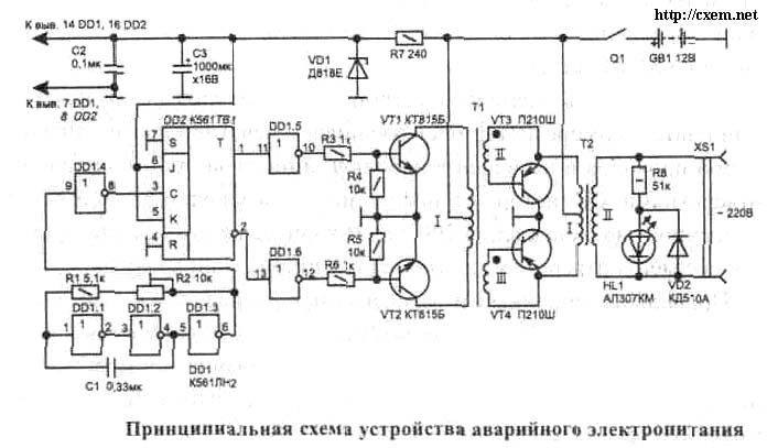
From the outputs of the trigger pulses arrive at the buffer logic elements DD1.5, DD1.6, which enhance the pulses current, and then fed through resistors R3, R6 to the base of transistors VT1, VT2. In the collector circuits of these transistors included half of the winding I of the transformer T1. With the windings II, III of the transformer T1 rectangular pulses arrive at the the base of transistor VT3, VT4. These transistors operating in key mode, alternately serves the supply voltage on one half of the winding I of the transformer T1. Polubotko the transformer is included in the emitter circuits of transistors, instead of the collector; this is done to ensure that the transistors VT3, VT4 type PS, in which case connected manifold, could be mounted on one without electric radiator isolation transistor package. It should be noted that in this case Polubotko the transformer T1 is (from the point of view of circuitry) could be included in the collector circuit of transistors. With the winding II of transformer T2 relieve tension 220 V 50 Hz, which is used to power appliances. This sinusoidal voltage from virtually no effect on the operation of electrical appliances. The transformation ratio of transformer T2 (the ratio of the numbers of turns of the winding II and half winding (I) equal 220/12 =18,3.
HL1 led indicates the presence of high voltage in the secondary winding of transformer T2. Diode VD2 protects the led from the reaction of the reverse voltage. Chip powered by a parametric voltage regulator, which is made on the Zener diode VD1 and the resistor R7. Voltage regulation is necessary in order to ensure the immutability of the oscillator frequency when the voltage of the battery. Capacitor NW smooths out the ripple voltage frequency of 50 Hz. Capacitor C2 bypasses high frequency random noise.
The details of the device. Instead chipset series C you can apply chip series 564, CR. Transistors VT1, VT2 can be any of the series KT815, CT, CT; VT3, VT4 - P with any letters and T, GT, T with any alphabetic indices. Application as VT3, VT4 silicon transistors undesirable because they are characterized more than germanium, the voltage drop across the transitions in the saturation state, which leads to considerable heat loss and reduces the coefficient the operation of the device. The Zener diode VD1 to replace DB, however, the temperature voltage stability with him a few below. Diode VD2 can be absolutely any.
Capacitor C1 should have a small temperature coefficient of capacitance, because it depends on the frequency stability of the oscillator. This condition is satisfied the types of capacitors K73-17, K73-24. The capacitor C2 - type KLS, K10-7B, km-5, Km-6. The oxide capacitor NW - C50-16, C50-24, C50-35. The trimmer R2 - type SP5-2, SDR-14; the remaining resistors C1-12, S2-23 or MLT. Switch Q1 - tumbler type TV 1-4 with four groups make contact; to increase switched current all four groups are connected in parallel. Socket XS1 - type RD. Transformer T1 is made on magnetic tape SHL 12x20. Winding I contains 500 turns of wire sew-2 0,21 with a branch of the middle; the winding II and III - 30 turns of wire sew-2 to 0.4. The same terminals of the windings II and III must to be marked (shown by dots). Transformer T2 is formed on the yoke SLH. Its winding I contains 96 turns of wire sew-2 2.5 with a branch of the middle; winding II - 920 turns of wire sew-2 0,56
As the battery battery GB1 can be used for automotive starter battery voltage 12 In, for example, ST. From the capacity of the battery depends on the time of continuous operation Converter to the load.
The design of the device arbitrary. Transistors VT3, VT4 must be installed on the heat sink the radiator area of about 200 cm^2. The circuit connecting the battery, power transistors, the transformer T2 must be met for wires with cross section not less than 4 mm^2 Device setup is to establish through resistor R2 adjusted the oscillator frequency is 100 Hz.
Publication: www.cxem.net