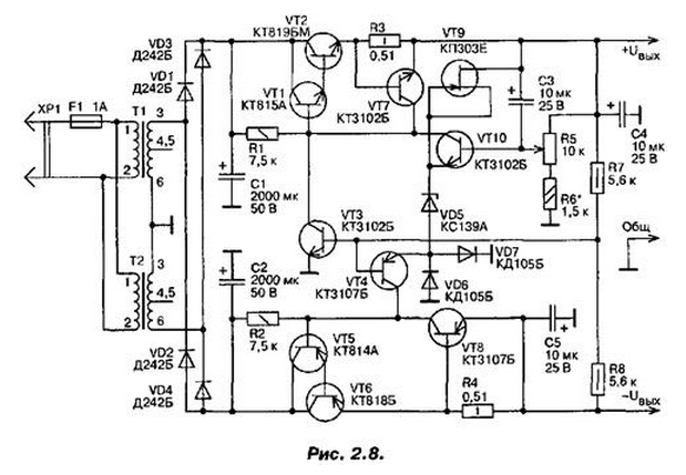
The power supply (figure 2 8) provides a bipolar output voltage which you can change from 5 to 25 V. the Maximum load current can reach 1 A. When exceeding this current or short circuit on the output device is triggered protection and output voltage sharply decreases simultaneously on both channels. The transformers T1 and T2 are included as a step-down, each of them "works" on both of the channel. Rectifiers diodes made on the VD1...VD4, rectified voltage smoothed by capacitors C1 and C2 are relatively large capacity.
Transistors VT1, VT2, VT10 is assembled by the compensatory scheme stabilizer voltage channel positive polarity, and the transistor VT9 and the Zener diode VD5 - source reference voltage for the regulator. Output the voltage adjust variable resistor R5.
Transistor VT7 and the resistor R3 constitute the node current protection. When the load current exceeds a given value, the transistor opens and the voltage regulator goes into constant current mode. In the negative polarity channel a voltage regulator is assembled transistors VT4...VT6, and the node current protection - on the transistor VT8 and the resistor R4.

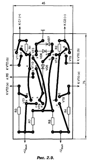
The printed circuit Board shown in Fig. 2.9.

Reference voltage for the regulator output voltage is stabilizer channel positive polarity, which through a resistor R7 is supplied to the base of transistor VT4. So when you change a variable resistor R5 voltage of positive polarity will change and the output voltage negative polarity. This change was synchronous and both output voltage were equal, resistors R7 and R8 are selected with identical resistances, and in the chain of Zener introduced anti-parallel included diode VD7 VD6 and.
ri normally operating power supply voltage, remove from the common junction point of the resistors with respect to a common wire, zero and the transistor VT3, the base of which receives this voltage, closed. Except these unified transformers, the unit can be used also ready transformers TC-31-1, or one transformer with a capacity of not less than 60 W with two secondary windings voltage on 27...30 V At a load current up to 1 A.
Transistor VT1 can be CHA...CTG, CTA...CTG, CTA, CTB; VT2 - CTA, CTP CTA, CTB, CTA; VT3, VT7, VTI0 - CTA...CTV, CTV, CTV, CTV...KTE; VT4, VT8 - GTC 107A GTC... K, CTV...KTE; VT5 - CTA...CTG, CTA...CTG; VT6 - CTA...CTG; VT9 - CPD, CPE, CPA, CPB, CPA, CPB. Diodes VD1...VD4 - D, DB, D, CDA...CDC or similar powerful; VD6, VD7 - KD105B, CDG, CDA, CDB, and other silicon rectifier diodes. The Zener diode VD5 - XA, XA, KS147A.
Powerful diodes VD1...VD4 can use without radiators, but the transistors and VT2 VT6 you must install on radiators with total surface area of at least 200 cm2. When checking work block if necessary to change the adjustment range of the output voltage you should choose a resistor R6. Value current protection operation can to set the selection of resistors R3 and R4.
Author: A. P. Seman


