


")

The appearance of the proposed unit with powered from the transformer. Tesla is shown in Fig. 1.
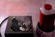
Fig. 1
The unit is assembled in the housing of a standard computer. BP. Its output is connected the primary winding of the transformer, consisting of five turns of insulated bonding wire section 2.5…4 mm2, wound on a segment of plastic plumbing pipe external diameter of 110 mm. The secondary winding frame - plastic bottle of kefir volume of 0.8 L. Enameled wire with a diameter of 0.2 mm is wound on it in a row turn to turn to fill (about 1000 turns). The lower end of this winding is grounded - connected to the third contact (RE) network "euroroute". The upper end of equipped with a copper pin, around which there are various high-voltage effects. The secondary winding is protected from mechanical damage and interturn breakouts with several layers of epoxy resin. Between primary and secondary windings mandatory air gap that is wide enough to exclude breakdown between windings and corona discharges.
The inductance of the secondary winding and its own capacity form of oscillatory contour, due to the resonance in which there is a multiplier voltage compared with the value calculated by only considering the relationship the number of turns of the windings, the analysis shows that the main factor that determines the resonance frequency of the secondary winding is its size.
To measure this frequency is quite simple. It is sufficient, as shown in Fig. 2, apply to the primary winding is made of the voltage from transformer tunable signal generator of G1.
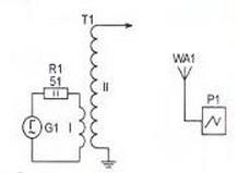
Fig. 2
Resistor R1 limits the current, its power should not be less than the power of the generator. Property location with a transformer set the oscilloscope connected to the input of the antenna WA1 - cut any wire length 100…200 mm Rearranging the generator, remove the dependency the magnitude of the signal on the oscilloscope screen frequency. For the above transformer it turned out such as in Fig. 3.
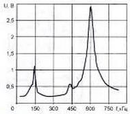
Fig. 3
The resonant frequency corresponds to the main maximum of the curve in this case is $ 600 kHz. Available on the Internet program of the calculation of the Tesla transformer gave similar results: 632 kHz. In the absence of the oscilloscope can be replaced by a simple indicator electromagnetic field, having collected according to the scheme shown in Fig. 4.
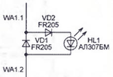
Fig. 4
Antenna WA1 is a two soldered to the pins of the diode VD1 and directed in different directions pigtail length of about 100 mm each. Resonance define the maximum brightness of the led HL1. The diagram of the power supply transformer. Tesla is depicted in Fig. 5.
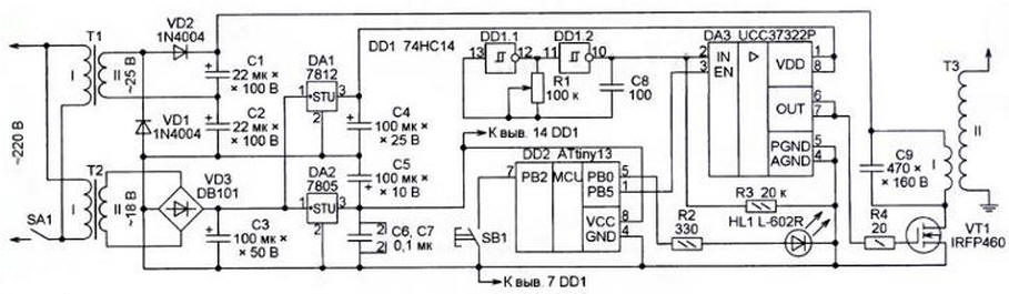
Fig. 5
T3 is actually the transformer. On the elements of DD1.1, DD1.2 assembled generator pulses, following a frequency close to the resonant frequency of the secondary the winding. Reinforced chip DA3 (driver field-effect transistor) and working in the key powerful mode field effect transistor VT1, the pulses are fed to the winding I of the transformer. Variable resistor R1 controls the frequency of the pulses, achieving the brightest luminescence gas-discharge (for example,"energy saving") lamps, located near of the transformer.
The microcontroller generates at its output P85 pulses which, acting on the EN input driver DA3, allow and prohibit the driver. These pulses modulate the pulse sequence supplied to the coil I transformer T3, and hence a high voltage across its coil II.
There are five modes of the microcontroller switching ring push the button SB1. Each transition is confirmed by the blinking of the led HL1, the number of flashes equals the number of the selected mode. In the first mode are generated pulses with a duration of 1 MS with pauses in between 8 MS. In the second pauses duration increased to 10 MS, in the third - to 12 MS, in the fourth to 14 MS, and the fifth - to 20 MS.
Regime change affects the nature of the sounds produced by electric discharges, and also on their number and length. The longer the pause, the more time to deinitialise air in a discharge to the beginning of the next burst of pulses a high voltage. changing the program can be modulated pulse a sequence of more complex signals.
The transformer T1 with a rectifier in the voltage doubling circuit of the diodes VD1, VD2 nourishes voltage 40…60 In the cascade FET VT1 there is another power transformer - T2. From him through the rectifier bridge VD3 and integral stabilizer DA1 12 V powered driver DA3. The output voltage stabilizer DА2 (5) intended for microcontroller DD2 and DD1 chip.
A drawing of the circuit Board unit shown in Fig. 6.
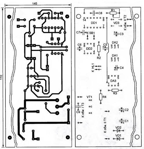
Fig. 6
Transistor VT1 is equipped with a finned heat sink. A significant portion of the surface fees free of components and circuit conductors. Here strengthen transformers T1 and T2. As SA1 used the switch that already exist in your computer the power supply unit, the housing of which is placed a charge. Its length (145 mm) as shown on the figure can be changed depending on the dimensions of the housing. If it has the fan can be activated by submitting a voltage of 12 V from the output of the stabilizer DA1. This will help to reduce the temperature of the transistor VT1, however, the stabilizer in this the case too is necessary to provide a heat sink.
Chip NC you can replace domestic CRT or other logical chip containing Schmitt triggers, inverters, elements, AND IS NOT, OR IS NOT. When the need for the free items you can collect the generator pulses, replacing the microcontroller. However, the opportunity will be lost quickly change modes and to create, changing the program microcontroller, new visual and sound effects.
Replacing the MOSFET IRFP460 should pick up to the allowable voltage for the source-drain not less than 200 V and a maximum drain current of at least 10 A. the Transformer T1 should to have a secondary winding with a voltage 20…30 V At a load current of 3 A. If there is a transformer with twice the voltage of the secondary winding, doubling voltage connected to the rectifier (diodes VD1, VD2, capacitors C1, C2) can be waived and apply conventional bridge rectifier.
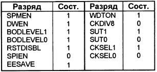
After manufacturing unit and install it programmed microcontroller configuration that must match shown in table (exactly as it is set at the factory), it is recommended not connecting to the power transformer. T3, to apply a voltage of 220 V, 50 Hz only the winding I of transformer T2. HL1 led should blink twice to confirm the functionality of the microcontroller.
Now you need to check the voltage at the output of the integral stabilizers DA1, DA2 and the presence of pulses at the inputs and the output driver DA3. On the oscilloscope screen, connected to the input IN (pin 2) should be rectangular the pulse amplitude of about 5 V, the frequency of which is adjustable variable resistor R1 in the range of at least 300…900 kHz. If not, you need to check the generator on the elements of DD1.1, DD1.2.
The parameters of the pulses received at the input EN (pin 3) driver from microcontroller, shall be as specified in the description of modes of operation block.
The output driver (findings 6 and 7) and the gate field-effect transistor VT1 needs be packs of high-frequency pulses with the corresponding selected mode the pauses.
Making sure everything is in order, you can connect to the unit transformer T3 and apply the supply voltage and the primary winding of the transformer T1.
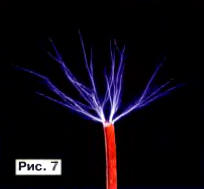
Placing near the winding II of the transformer T3 energy saving lamp and rotating the slider of the variable resistor R1, you need to make the most vivid glow the lamps. Around the pin connected to the upper output winding, should be formed discharges (streamers), similar to that shown in Fig. 7.
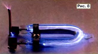
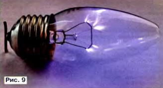
Glow'm not connected, but simply held in the hand discharge lamps - the most simple effect that occurs when working with the Tesla transformer. It is the result of exposure to the gas inside the bulb of the high-frequency electromagnetic the field surrounding the transformer. The design effect observed at a distance of 20 cm from the transformer and produces a large impression on the audience who are not familiar with his essence. Discharges can be observed and inside lamps filled with gas under relatively high pressure (Fig. 8), including conventional incandescent bulbs (Fig. 9). but for that they need to connect one output to the transformer output.
Length called filamentary streamers of high-frequency discharges in air, arising during operation consider the transformer reaches 20…30 mm. It is believed that it is numerically equal expressed in kilovolts amplitude developed on the secondary winding of the transformer high-frequency voltage. it is interesting to observe the color change streamers when applied to the tip of the pin, which ends winding, various chemical substances, such as salt.
Level when operating the device in question arise on and off with a frequency of the modulation applied to the transformer pulse sequence. In the result of noises, the fundamental frequency which is equal to the frequency the modulation. Because each pause streamers are extinguished, and arising after often go on other ways apparent number of streamers increases.
If you set on the edge of the high voltage pin light wire with the chopper curved in a horizontal plane in different directions ends, these ends encounter level. The resulting ions, starting from the ends turntables, and bring her into motion. Of course, that this model of ion engine earned, the turntable should be very light and well balanced.
A positive feature of the described source, ensuring the safety of work with him is the lack of inside high DC voltage. Occur when the transformer. Tesla high frequency practically safe for experimenters, because at the discharge, under the body of the person, his current, because it is high frequency, occurs only in the skin, not reaching vital important organs. It is known in radio engineering phenomenon is called skin effect and occurs when the flow of high frequency current on any conductors. Of course, such a current can to cause burns, but it happens only when the level is many times more power. The presence in the described device of the microcontroller gives considerable scope for the experiments.
Changing the program, you can, for example, without making any changes to the schema, play simple rhythms and melodies, and replacing the microcontroller more productive, to connect a MIDI keyboard or control the device using the computer.
Since the transformer. Tesla is the source of powerful electromagnetic fields, not it is recommended to turn away from expensive electronic equipment or from the carriers of important information.
Author: D. Eliseev