


")

This power supply is simple to repetition, are protected against accidental short circuits, has a smooth adjustment of the output voltage from scratch, the collectors of the transistors are mounted directly to the heat sink or the chassis (chassis).
The unit consists of step-down transformer, rectifier, comparing the device to the operational amplifier, his current consumption controls composite transistor and node protection (Fig. 1).
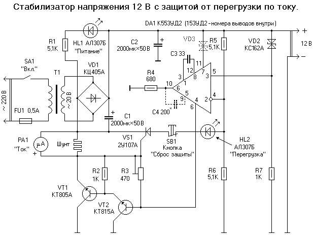
Fig. 1.
Step-down transformer must be checked, to give them power. For this purpose, the primary winding of include the fuse in the supply 220 volt, pre-taping over all exposed wiring. AC voltage at the secondary winding should not to exceed 20 volts, or after the rectifier DC voltage at an electrolytic capacitor will exceed 30 volts, the limit for the chip the operational amplifier. In parallel to the terminals of the secondary winding of the transformer connect a voltmeter and a momentary short-circuit resistor powerful resistance of 20 Ohms. The current through the resistor will be approximately 1 amp. Usually this is enough, but "matter of taste". If the voltmeter has changed slightly and this capacity is satisfied, the check is complete.
In the rectifier is better to use the micro-CC-402 or KC-405 with any letter index. Then the DC voltage at the output will be more "beautiful" due to the same the parameters of the diodes of the bridge. When high currents of the rectifier unit the bridge is assembled from separate powerful diodes.
Comparing the device (see Fig. 1) consists of an operational amplifier DА1 and the measuring bridge, formed by resistors R5-R7 and Zener diode VD2. The voltage change on the output of the power supply leads to the unbalance of the measuring bridge. Operational the amplifier amplifies the offset voltage by the voltage on the load the resistance R4, but since the load is constant, then changes the current passing through the chip. This current, as best suited to manage the control transistor as the transistor, in General, the current element. The idea non inclusion of the operational amplifier is taken from [1]. In comparing the device can be applied to any operational amplifier, especially if the unit will be used as the unregulated voltage regulator in any device. The voltage at the output of the block will be equal to twice the voltage stabilization of the Zener diode used (this ratio can be changed resistors R5 and R6). If you need to stabilize the voltage of more than 30 volts, then you need to install the Zener diode VD3 (shown by a dotted line), which repay the excess voltage at the shelter. In this case, the resistance of the resistor R7 should to be designed for a nominal operating current of the Zener diode VD2. Operational the amplifier without feedback can be excited and then you will need to enter the capacitor C4.
Not all operational amplifiers suitable for adjustable version of the unit (see Fig. 2). You need to trace, so when reducing the output voltage to "zero" potentiometer R7 process stabilization is not frustrated. Otherwise, the output unit displays the full voltage from the rectifier.
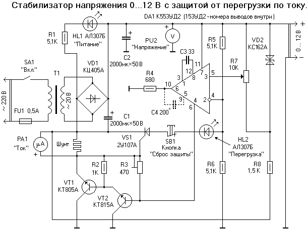
Fig. 2.
The protection node consists of a shunt and the SCR WA. The current passing through the shunt, it creates a proportional the voltage drop. As soon as the voltage reaches a certain level, SCR will open and dis-balances balancing the bridge R5-R8 (Fig. 2). Then the compound of the transistor VT1-VT2 is closed and the current through the load block will cease. To return protection to its original state button SB1. Here it should not be a toggle switch or switch: you can forget to enable protection. When the necessity of obtaining the maximum current you can just hold the button down. As the shunt used cut manganin wire. Section and the length of the wire is chosen experimentally depending on the required current and threshold protection. SCR WA sensitivity, rapidity and safe operation proved to be the most successful choice. Other triacs not given the desired result.
Composite transistor can be assembled from any of the transistors in compliance with the General rules, for example: VT1-CTA, VT2-CTA. Trimming resistance R3 (Fig. 1) adjust the composite transistor for maximum impact current. To do this, load resistance (for example, 12 Ohm) short to short circuit the output of the supply and install R3 is lower the deviation of the output voltage.
On the basis set out was assembled bipolar laboratory power supply (see Fig. 3 and photo 1-3). Top under the scheme, the stabilizer is convenient to use without protection. Together with the lower the stabilizer can get the voltage to 25 volts, plus overload protection. Transistor VT1 must be isolated from the radiator of the mica strip.
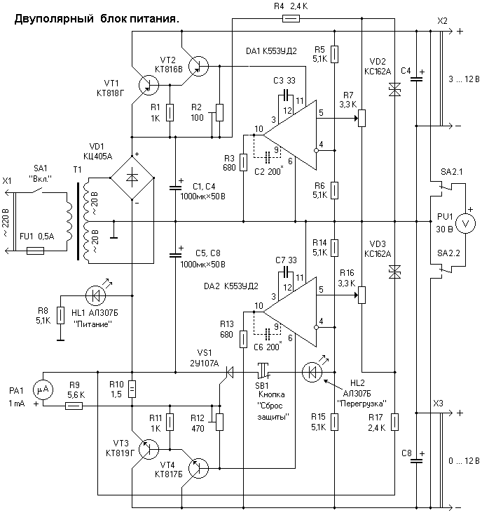
Fig. 3.
Details of the power supply unit is assembled on printed circuit Board size h mm Housing unit made of a unilateral foiled fiberglass size HH mm body Parts held together with tin. The upper cover body reinforced triangular the gusset. Front and rear walls secured to the pallet boxes. They drilled holes and soldered from the inside nut M3 for mounting cap.
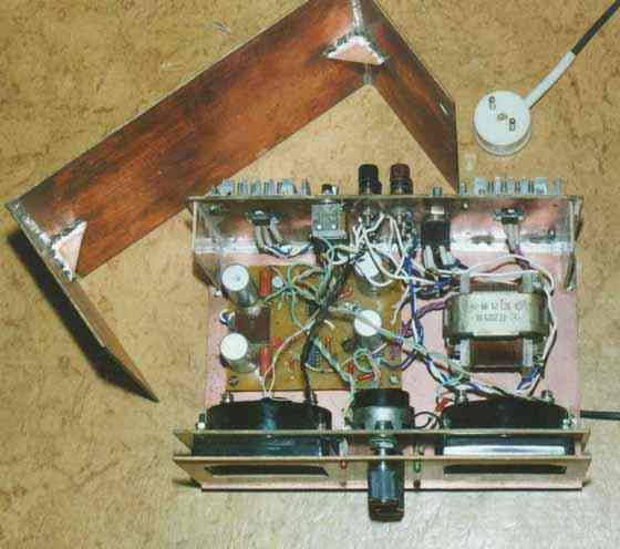
Fig. 4.
False panel is attached to the front the panel using a screw and nut through the hole drilled in the middle. On false panel displayed on the LEDs: red - lights up when the protection is activated, green - indicates the on state of the block in the network. For voltmeter and milliammeter cut-out holes. Milliamp regulated shunt to full deflection and protection at a current of 300 milliamps. This the protection is triggered immediately and not saved a single device.

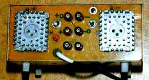
Fig. 5.
The rear panel contains radiators with transistors VT1 and VT3, fuse, terminals output voltage, the switch of the power supply unit to the network, the toggle switch voltmeter, button "Reset protection".
Literature
Author: M. Fayzullin (UA9WNH/9), This email address is being protected from spambots. You must have JavaScript enabled to view it. ; Publication: www.cxem.net