This
wireless microphone operates in the band 100-108 MHz with frequency modulation.
The reception range of the signal is about 50 m. the device is Powered by power supply from 1.5 to 9 V. the
Schematic diagram presented in Fig. 7. The transmitter consists of a single-stage audio frequency amplifier and single-stage high-frequency generator. The master oscillator is assembled on a common scheme. The carrier frequency is determined by the elements C4, L1, C5 and capacitances of the transistor VT2. The modulating amplifier is made on the VT1 transistor KT315 type. The amplified signal via the capacitor C2 is supplied to the emitter of the transistor VT2 KT315 type. Modulating voltage causes a change in the junction capacitance base-emitter of the transistor VT2, and thereby performs frequency modulation of the master oscillator. The signal from the generator through a capacitor C6 is supplied to the antenna, which is used as the wire cut a length of 10-40 cm Coil L1 frameless wound on the mandrel with a diameter of 3 mm and consists of 4 turns of wire sew 0.6 mm, the winding pitch of 2 mm.
configure wireless microphones is compression or stretching of the turns of the coil L1 to receive the signal free from broadcasting stations site УSW range of the broadcast receiver.
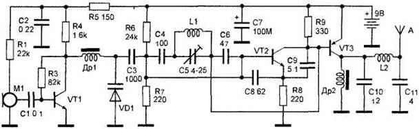
Figure 7. Radio transmitter with frequency modulation.


")
