The transmitter operates in the range of 65-73 MHz with frequency modulation. The range in the use of framework compact antenna is about 150 m. the Duration of operation
of the transmitter when using batteries "Crown" is 30 h.
Schematic diagram of the transmitter is presented in figure 9. The low-frequency signal of the microphone M1 type FEM-3. "Pine", etc. is amplified by two-stage low-frequency amplifier with direct links. Amplifier transistors VT1 and VT2 KT315 type. The mode of operation of the amplifier is set by resistor R2. The master oscillator is made on the VT3 transistor KT315 type. Customizados circuit is connected to the base of transistor VT3 through the capacitor C6 of small capacity. Capacitors C8, C9 form a feedback circuit. The generator circuit consists of the inductance L1, capacitor C5 and two, counter, diode type CD. Under the action of the modulating voltage capacitance diodes VD1, VD2 change. Thus, a frequency modulation
transmitter. With the generator output modulated signal supplied by the amplifier.
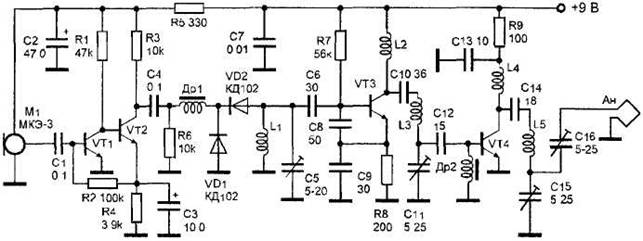
Figure 9. Radio with compact loop antenna.
The output amplifier is made on the transistor VТ4 KT315 type. It works with high efficiency in the mode "C" class. The amplified signal enters the loop antenna is made in the form of a spiral. The spiral may be of any shape, it is important that the total length of the wire was 85-100 cm, wire diameter 1 mm Chokes DR1, dr2 do - all, with an inductance of about 30 µh. Coils L1, L2, L3, L4, L5 - frameless, 10mm diameter. Coil L1 has 7 turns. L2 and L4 - 4 turns. L3 and L5 - 9 turns. All coils are wound wire sew 0.8 mm. setting the transmitter has no peculiar features.


")
