


")

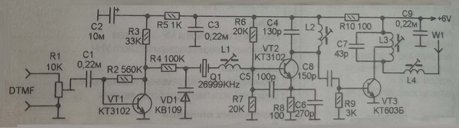
Here is a diagram of receiver and transmitter for wireless control. The transmitter operates at a frequency 26999 kHz and is designed to transmit DTMF code. The range of the described apparatus control about 300 meters.
Schematic diagram of the transmitter shown in figure 1. The encoded DTMF signal through the tuned resistor R1 and the capacitor C1 is supplied to the amplifier consisting of transistor VT1. With the collector of the transistor through a resistor R4 amplified signal is supplied to the varicap VD1 to modulate the transmitter. The master oscillator is built on the VT2 transistor whose frequency is stable quartz frequency 26999 kHz. On the VT3 transistor is made cascade power amplifier with output of which is modulated by the signal extending through the coil L4 is supplied to the antenna and radiated into space. The circuits L2, C4, and L3, C7 transmitter tuned to the crystal frequency.
Schematic diagram of the receiver for the radio shown in figure 2. It is built on the superhet circuit. The structure of the receiver is chip IC1 MS which is its Foundation, it made the frequency Converter, amplifier the if limiter and frequency demodulator. The received signal by the antenna is amplified by radio frequency amplifier and is input to the chip. The frequency of the local oscillator of the receiver is set by the loop L2, C10. The DTMF signal is taken from pin 9 of the chip and then it is fed to the decoder.
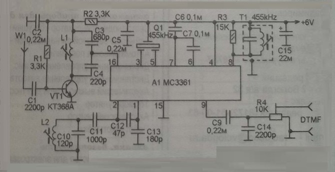
For winding coils used plastic frames with trimpot core of carbonyl iron, the diameter of the armatures 6 mm. transmitter Coil L1 consists of 30 turns of wire sew 0.12, coils L2 - 6 turns, L3, L4 for 10 turns, L3 branch of the middle, the wire coiling sew 0.31. Coils L1 and L2 of the receiver wound wire sew 0.12, each has 6 turns. The T1 circuit to the frequency of 455 kHz is applied from a faulty receiver.