


")

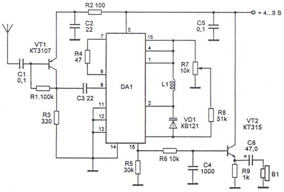
Figure 24. The radio on the micro-CHA.
The signal from the antenna is input to an aperiodic high-frequency amplifier, which is made on the type of transistor VT1 CT. The amplified signal via the capacitor C3 is input to the micro-DA1. B it is the amplification and demodulation of FM signal radio stations. The frequency of the local oscillator is determined by the parameters of the circuit L1, VD1 and the condenser, located in the micro. Restructuring within the range produced by changing the voltage on the varicap VD1, which is removed from the engine resistor R7. The voltage across the resistor R7 is supplied from an internal regulator of the micro. The output voltage of the LF output of the micro is input to the emitter follower transistor VT2 KT315 type. The signal is fed to the headphones or B2 to the input USC with sensitivity not worse than 50 mV. Transistor VT1 can be replaced by CT, KT361. Transistor VT2 KT3102. Instead of the varicap VD1 can be used SW109, SW122, SW123. Coil L1 frameless wound on the mandrel with a diameter of 3.5 mm. Coil L1 contains 7 turns of wire sew 0.4 mm for the range of 68 to 80 MHz or 3 coils - for the range 80-108 MHz. If you intend to use the receiver to work with a single microphone, it is possible to apply the preset. It is possible to exclude from the scheme elements VD1, R7, R8, and parallel to the coil L1 to enable the trimmer capacitor 4-30 f, which will cover the entire desired range.