The radio microphone, schematic diagram of which is shown in Fig. 8. operates in the frequency range 65-108 MHz with wideband frequency modulation. This allows you to take the signal from the
radio microphone on a conventional FM receiver of this range. The range of 150-200 m. the Length of the working time with battery type "Crown" - about 10 hours of low-Frequency oscillations from the output of microphone M1 (type FEM-3, M1-B2 "Pine" and the like) through the capacitor C1 is fed to the audio frequency amplifier, made on the VT1 transistor KT315 type. The amplified audio signal taken from the collector of transistor VT1, through the inductor DR1 affects the varicap VD1 (type SW109А), which performs frequency modulation of a radio signal generated by high frequency generator. The RF generator is assembled on the VT2 transistor KT315 type. The frequency of this oscillator depends on the parameters of the circuit L1, C3, C4, C5, C6, VD1. The RF signal taken from the collector of transistor VT2, is amplified by a power amplifier transistor VT3 type KT361. The power amplifier has a galvanic connection with the reference generator. Amplified high-frequency voltage is allocated to the throttle DP2 and enters the U-shaped contour, which is made on the elements C11, L2, C10. The latter is configured for transmission of the main signal and the suppression of many harmonics appearing at the collector of the transistor VT3. The radio microphone is assembled on the circuit Board size h mm antenna mounting cut wire of length 25 cm All items are small. Resistors - type MLT-0.25, the capacitors C50-35, km, KD. Instead of the varicap VD1 type SW109А you can use the varactors with another letter index, or for the varicap type SW102. Transistors can be any letter index. Transistors VT1 and VT2 can be replaced KT3102, KT368, and the transistor VT3 - CT, CT, CT. Chokes DR1 and dr2 do wound resistors MLT 0.25 resistance greater than 100 ohms wire sew 0.1 in 60 turns each. Coils L1 and L2 frameless, with a diameter of 5 mm. Coil L1 - 3 turns, the coil L2 is 13 turns of wire sew 0.3. Configuring
wireless microphones is reduced to setting the frequency of the master oscillator, corresponding to a free space УSW FM band, the capacitance of trimmer capacitor. Stretching or compressing the turns of the coil L2 is configured transmitter to maximum power of the RF signal.
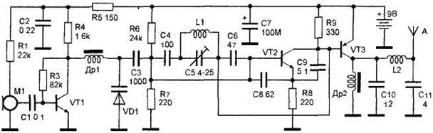
Figure 8. Radio transmitters with wideband frequency modulation.


")
