


")

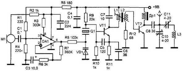
Figure 14. The radio transmitter, the frequency of the master oscillator which is stable quartz resistor.
This device works in the range УSW FM frequency modulation, i.e., its signal can be received at any receiver range 65-108 MHz. The operating range is about 300 m. the master oscillator is made on the type of transistor VT1 KT368. In this scheme can be used as the quartz resonators at frequencies 22-36 MHz. The circuit, consisting of coil L1 and capacitor C7 is configured at the third harmonic of the crystal. It is preferable to use a resonator, tuned to the third harmonic of the series resonance, because it is easier to obtain the necessary for the normal operation of the receiver frequency deviation of 50 kHz. Quartz resonator is connected to the base of transistor VT1 and the varicap VD1 and operates the oscillator circuit, comprising a capacitance C5 and circuit "a capacitive type, which ensures high frequency stability. The modulating amplifier is realized by operational amplifier DA1 type CRUD. At its input receives the low-frequency audio signal from the electret microphone M1 with built-in amplifier type FEM-3. Operational amplifier providing the output undistorted audio frequency voltage with an amplitude of about 3 V, which is sufficient, when used as the modulating element of the varicap type SW104А to achieve a frequency deviation of about 40-50 kHz. The mode of operation of the operational amplifier is set by resistors R1, R4, and R3. Chip DA1 can be replaced by COD, CRUD - in the latter case, the resistor R3 from the circuit to be deleted. Modulated frequency signal from the master oscillator circuit L1, C7 through coupling coil L2 is input to the power amplifier is performed on the transistor VT2 type CTA. The power amplifier operates with high efficiency in the mode "C" class. It boosts the signal up to 150 mW. Therefore, when using instead of hanging or whip antenna with a length of 1 m coil L3 with a diameter of 3 m (Fig. 15), containing 7 turns of wire sew to 0.8, the efficiency is not worse than the standard version-with cable length of 1 m and a capacity of about 30 mW. This power is sufficient for stable signal reception at a distance of 150 m. the length of the winding coils L3 - 5 cm used In the construction of resistors MLT-0.125, capacitors type CT. CD. K50-35. Choke DR1 wound on a resistor is 0.25 a resistance greater than 100 ohms. It contains 60 turns of wire sew 0.1 mm. Coils L1 and L2 wound on a polystyrene frame with a diameter of 5 mm with brass podstrasnickou. Coil L1 (figure 14) contains 10 turns of wire sew 0.31 mm, coil L2 - 5 turns of the same wire. The design of the coil L3 shown in figure 15.
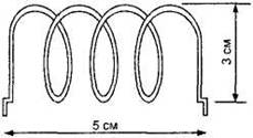
Figure 15. The design of the coil L3.
Setting low-frequency part of the transmitter has no peculiar features. The transmitter is set up according to the standard technique with the use of the indicator of the field strength and control of the radio. Circuit C7, L1 is set so as to ensure the stability of the generating sets of the cascade. When connecting wire cut length of about 1 m to the point A of the antenna after disconnecting the capacitance C10, C11 and L3, on measuring devices are making the transmitter output power of about 150 mW. That's enough power to receive a signal at a receiver with a sensitivity of 5 μv/m at a distance of 500 m in urban environments.