The device described below is a
transmitteroperating in the range of 27-28 MHz with amplitude modulation. Range of up to 100 m.
a Schematic diagram of the device shown in figure 6.
The transmitter consists of a high-frequency generator, assembled on the transistor VТ2 KT315 type, and single-stage audio frequency amplifier transistor VT1 KT315 type. The input through the capacitor C1 receives the audio signal from the microphone M1 type "Pine". The load of the amplifier comprise a resistor R3 and a high-frequency generator connected between the plus power source and the collector of the transistor VT1. With the gain of the signal voltage at the collector of transistor VT1 is changed. This modulated signal and the amplitude of the carrier signal generator of the transmitter radiated by the antenna. In design, the resistors MLT-0.125, capacitors - K10-7V. Instead of transistors KT315 you can use KT3102. Coil L1 is wound on a frame made of polystyrene with a diameter of 7 mm. It has rigged the ferrite core IN diameter of 2.8 mm and a length of 12 mm. Coil L1 consists of 8 turns of wire sew 0.15 mm. Winding turn to turn. Choke DR1 wound on the resistor MT-0.5 resistance greater than 100 ohms. Winding of the inductor consists of 80 turns of PEV of 0.1. The antenna can be made of elastic steel wire of length 20 cm When the setting frequency is set by adjusting the inductance of the coil L1. After adjusting the trimpot coil core is fixed paraffin.
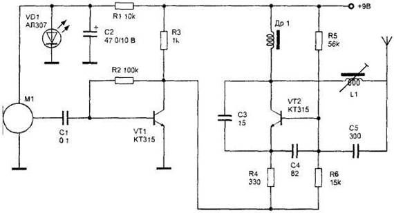
Figure 6. Radio transmitter with amplitude modulation.


")
