


")

Diagram of the microtransmitterperformed on the transistor, shown in Fig. 3. Modulating the voltage taken from the electret microphone MKE-3 (FEM-333, FEM-389, M1-A2 "Pine"), through the capacitor C1 is supplied to the base of transistor VT1, which made the master oscillator. Since the control voltage applied to the base of transistor VT1, by the voltage of mixing at the transition base-emitter and, consequently, the capacitance in the circuit, the base-emitter, which is a component of the oscillating circuit of the master oscillator is frequency modulation of the transmitter. This circuit also includes an inductor L1, which is set at a high frequency between the base of transistor VT1 and weight, and the capacitors C3 and C4. The capacitor C4 is included in purpose of the feedback capacitive treatacne, being one of the shoulders of the divider So-C4, and voltage feedback. The capacitance of the capacitor C4 allows you to adjust the level of excitation. To avoid the influence of the shunt resistor R2 in the emitter circuit of the transistor VT1 to a resonant circuit, which can cause excessive expansion of the bandwidth of the resonance curve, in series with the resistor R2 is a choke DR1, blocking the passage of high frequency currents. The inductance of this inductor should be about 20 µh. Coil L1 is frameless, with a diameter of 3 mm wound wire sew 0.35 and contains 7-8 turns. To obtain the maximum possible power is necessary to choose the generating element (the transistor VT1) and to establish the optimal mode of operation of the generator. For this it is necessary to use transistors, the upper frequency limit which must exceed the operating frequency of the generator is not less than 7-8 times. This condition most closely correspond to the transistor type p-p-p KT368, but you can use more common transistors KT315 or KT3102.
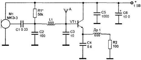
Fig. 3. Microtransmitter with frequency modulation.