


")

Despite the predictions of skeptics, the 16-bit TRS "Sega Mega Drive II continues to surprise with their longevity. Given the availability and wide selection cheap gaming cartridges, it's still a welcome gift for younger children of school age. It can be considered a champion by the number of known variants execution. The article considers the history of the development of these TRS and distinguishing characteristics of their versions, including the latest releases.
The Japanese company SEGA Enterprises Ltd. in 1987, going through hard times [1]. Her eight-bit console Sega Master System (SMS) significantly lagged behind the popularity from the "Nintendo Entertainment System" (NES) - the progenitor of the "Dendy". The issuing firm NES Nintendo controlled 92 % of the U.S. and 95 % the Japanese video game market. In the USA, every third family had a TRS, the vast most cases - NES.
To change this situation, the firm SEGA has gathered a strong team of engineers under the leadership of Hideki Sato (Hideki Sato), putting her in a year to submit the world of 16-bit TRS. Prototype was a slot machine "System 16" firm SEGA. It was borrowed from a dual-processor architecture: MC68000 (Motorola) and Z80 (Zilog).
Official date of birth "Sega Mega Drive" (MD) - October 29, 1988 in this day the first copies went on sale in Japan. Presentation on the American market was held on 14 August 1989, under the brand name "Genesis", as the word "megadrive" was already registered with one of the firms in USA your name.
First sales of MD in Europe took place in November 1990 in England. TO TRS made over a dozen games developed by Namco, Electronic Arts, Konami. Considering compatibility (through the adapter) ink cartridge for SMS, the total number of available consumer games reached hundreds. Good performance, rich color palette, stereo sound, a variety of peripherals - here is a list of advantages of MD. But she became the first public 16-bit TRS.
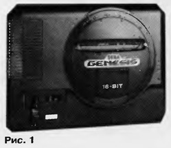
Various options MD carried the brand designation "MK-1601-XX". Were released regional versions: Japanese, American, European, Asian. They are all - in rectangular case dimensions 285x225x50 mm (Fig. 1 - TRS American option), differing in the television signal formats (PAL or NTSC), languages inscriptions, details of the appearance, the power supply for 120 or 220 V. In the European MD was not 9-pin connector "EXT" in the Japanese version intended for connection of the modem. MD was equipped with a Jack for connection head stereoleto and slide volume control. Features circuitry and repair of this TRS covered in [2].
In 1993, after five years of the onset of MD, the company SEGA has released a new, cheaper modification consoles Mega Drive II (MD2) and its American option "Genesis-2", while maintaining software compatibility "bottom-up" with MD.
The main differences MD2 MD:
- no jacks for headphones and volume control;
- connector A/V OUT" outputted stereo sound;
- internal RF modulator replaced external;
- added joystick button "X", "Y", "Z", "MODE";
- software procedures separated "cold" and "warm" start;
- intended to check the compliance of regional belonging and cartridge console.
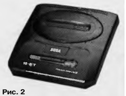
Brand name model number MD2 - MK-1631-XX", though there are other, for example, MK-1632-XX", "NA", "KW-501". In Fig. 2 shows the appearance of the European version of MD2 in a uniform square frame sizes 210x210x50 mm.
In 1992-1994 worldwide 16-bit TRS company SEGA were at the Zenith of fame. A little later the palm in terms of sales intercepted TRS "Super Nintendo", then came the time 32-bit "Sony PlayStation". Since 1996, the center of the zone home IIP company SEGA has moved to Brazil and China, and then to CIS
At the end of 1997 there was an attempt of revival of MD2. Firm Majesco (USA) released under license Severability option IWP called "Genesis-Z". In there is no system connector, which eliminates the TRS connection with MegaCD, simplified some of the functions assigned to the Z80 processor. In appearance the new model - a cross between a hockey puck and a CD player. Advantages "Genesis" and "Genesis-2" steel relative cheapness (30…50$. USA) and the opportunity to work with Japanese brand's cartridges.
The company SEGA has officially stopped support for their 16-bit TRS in 1998 In just 10 years, has sold approximately 30 million consoles created for them more than a thousand games and three thousand varieties of cartridges.
Some of the original modification. Among them, "Sega Nomad" - portable MD2 with built-in three-inch LCD, "Wondermega" - symbiosis MD2 and MegaCD-oriented karaoke and playing music MIDI files "Medals" - a hybrid computer IBM PC-386 and MD2, designed mainly for development of game software.
VARIETIES MD2
The vast majority of common in the CIS countries EMU - Asian and the European version of MD2. They should be called MD2-compliant because they are not built on proprietary VLSI SEGA315-xxxx, and in their copies of the various manufacturers. Occasionally there are licensed MD and MD2 (both versions produced up to 1995). American EMU Genesis, including "Genesis-Z", in the CIS countries was not widespread.
MD2 is conventionally divided into three generations by year of release: 1993 to 1996 - first, 1997 and 1998 - the second, 1999, and later a third. They differ in mainly the degree of integration and the number of VLSI. For example, since MD2 second generation, core processor MC68000 and Z80 Packed in one VLSI-"multiprocessors". Among the repairmen she is known under the names "HH" or "HH", though actually it is the date of manufacture of the chip: the first two digits - year (1997 or 1998), the following is the week ordinal of the year.
Find out on the label on the underside of the hull, what generation is console, not always. The buildings MD2 standardized and interchangeable, therefore, one should not be surprised to find, for example, in a case called NAA cost TRS first generation.
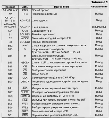
To accurately determine the type and generation of MD or repaired easy by MD2 positional designations and types of installed on its motherboard chipsets. Table.1 contains information about the most common options, though there are other. Below are the circuits of various functional purposes used in MD and MD2. In brackets are the names of the manufacturers chips.
(click to enlarge)
CPU: MC68000P, MC68000L, MSSR (Motorola); SCN68000 (Signetics) - DIP-64. HD68HC000CP (Hitachi); MC68000FN (Motorola) - in QFP-68.
Additional processor: Z84000 (GoldStar); Z80A (Zilog); Z80CPU (Mostek); Z80ACPU (STMicroelectronics); LH0080 (Sharp); TMPZ84C00 (Toshiba); mPD780C (NEC); KP1858BM1 (Russia) - DIP-40. Z84C0008 (Zilog); 84C00AU-6-in QFP-44.
Video encoder: SAM (Sony); MB3514 (Fujitsu); KA2197D, KA2198BD (Samsung) - the housing SOP-24. CXA1145P (Sony) - DIP-24. MC13077P (Motorola) - in the DIP-20.
Audio-RAM: SRM2064, SRM2A256 (Seiko Epson); MK48H64 (STMicroelectronics); TC5564, TC5565 (Toshiba); MB8464 (Fujitsu); HY6264 (Hyundai); HM6264 (Hitachi); CY6264 (Cypress); MT5C6408 (Micron); M5M5178 (Mitsubishi); CXK5863, CXK5864 (Sony); MPD4364, MPD43256 (NEC); TMM2064; HSRM2264; MCM6264 (Motorola); UM6264 (UMC); AKM6264 (Asahi Kasei); LC3664 (Sanyo) - in the case SOP-28.
Video RAM: NM (Hitachi); mPD41 264 (NEC); M5M4C264 (Mitsubishi); MB81461 (Fujitsu); MT42C4064 (Micron); V53C261 (Mosel-Vitelic); TMS4461 (Texas Instruments) - DIP-28. HM53462 (Hitachi) - DIP-24. MSM54C864 (OKI) - in the case SOJ-40.
Main RAM: NM, HM66203 (Hitachi); mPD43256 (NEC); KM62256 (Samsung); SRM20256 (Seiko Epson); CXK58257 (Sony); ATT7C256 (AT&T); CY7C199 (Cypress); IMS1630LH (STMicroelectronics); UM62256 (UMC); HY62256 (Hyundai); MB84256 (Fujitsu); M5M5256 (Mitsubishi); MS62256(Mosel); MCM51L832 (Motorola); GM76C256 (GoldStar); Idt71256 (IDT) - in the case SOP-28. LH52258D (Sharp); 61256PT - in the DIP-28, TC511632FL (Toshiba) - in the case SOJ-40.
Sound channel: NAR (Hitachi); MPC324C, MPC3403C (NEC); SM8652; ICPA324; KA324 (Samsung); KIA324P (KEC); LM324, MC3403P (Motorola); CA324G (RCA) - in the case DIP-14. KA324D (Samsung); LM324D (Texas Instruments); LM324M (National Semiconductor) - in the case SOP-14.
USC of stereoleto: SHAR, CXA1634P (Sony) - DIP-16. LM358 (Texas Instruments, On Semiconductor, Philips, National Semiconductor, STMicroelectronics); GL358 (Hyundai); ICPA358; KA358 (Samsung) - in the case DIP-8.
Stabilizer +5 V: L7805 (STMicroelectronics); LM7805 (Fairchild); NY7805C; OTI7805; KA7805 (Samsung); KIA7805 (KEC); ML7805; AN7805 (Panasonic); UB7805; uA7805 (National Semiconductor); HSMC7805; GL7805 (Hyundai); UTC7805 (Unisoniс Technologies); UC7805 (Texas Instruments).
Chip one and the same purpose in the same buildings, released various firms, as a rule, used interchangeably. With the advent of new models IWP the list continues to grow.
On consoles first generation MD2 discussed in [2]. Scheme and detailed methodology repair second generation MD2 is given in [3, 4].
The scheme of the third generation MD2 - in Fig. 3. This is not an official document of the company SEGA, as a result of the analysis device consoles, had been in the hands of the author. On this figure schematically depicts the location of major components and consoles shows the appearance of its connectors.
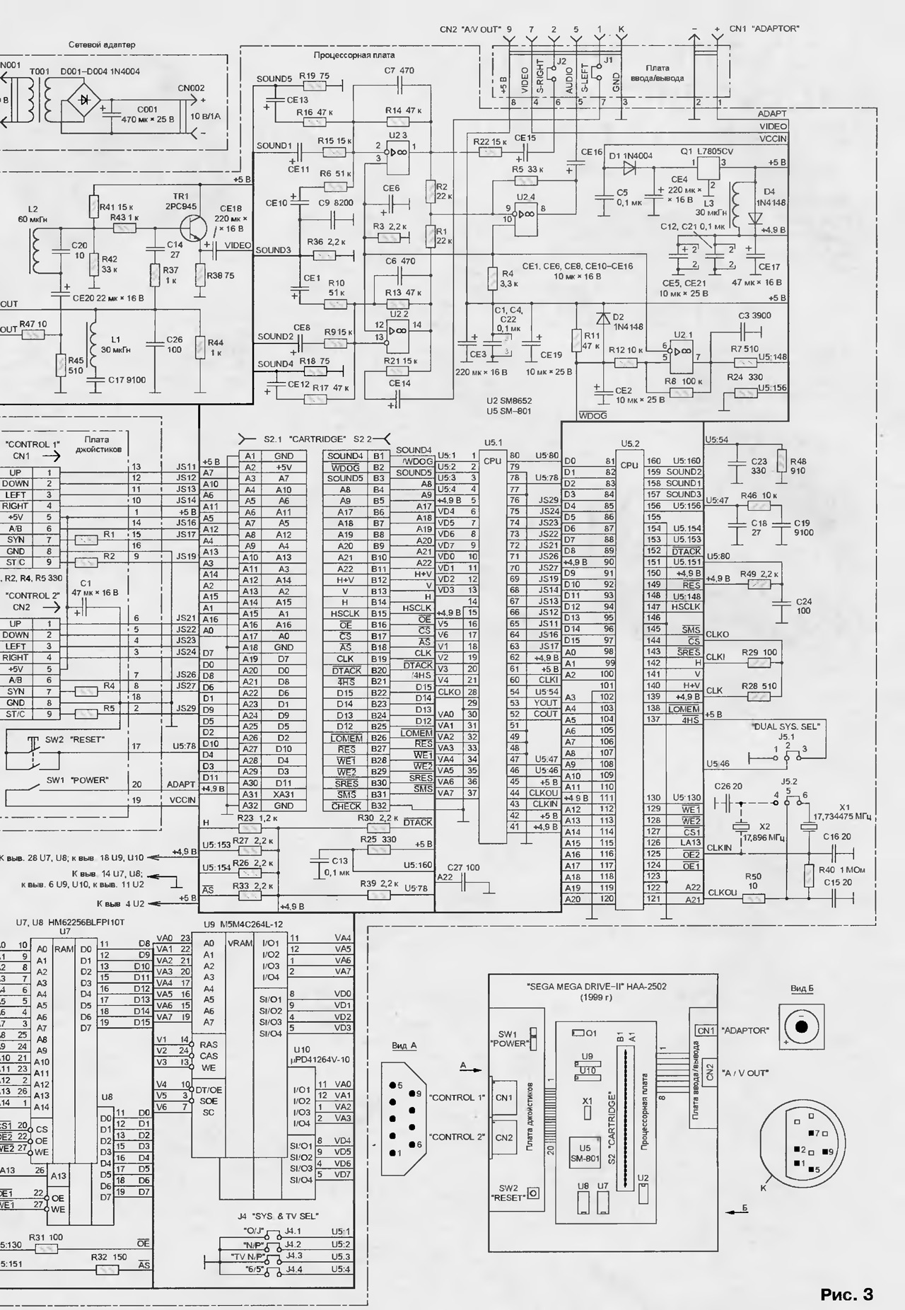
(click to enlarge)
In everyday life like a video game console is sometimes called a single-chip, since all the main functions of the single IC U5. It interacts only with the main RAM volume CH bit (chip U7, U8) and video RAM K bits (chips U9, U10). The audio channel is made at OS U2.2 - U2.4.
Like IWP previous generations, the SOUND signals 1 and SOUND2 - weekend respectively the left and right channels of a music synthesizer, functionally similar to the chip by the Yamaha YM2612, but are all in the same VLSI U5. Signal SOUND3 - output channel PSG (Sound Generator Programming). It a four-part sound like a "Dendy". The prototype of the PSG was the chip SN76489 by Texas Instruments. Bred to connector S2 "Cartridge" chain SOUND4, SOUND5 - technological inputs audio channel. They serve to validate without opening the IWP.
OS U2.2 and U2.3 covered by the negative OS on circuits R13С6 and R14С7. The upper bound the bandwidth of these cascades is 7.2 kHz. To extend the streak it is recommended to reduce to 200 pF, the values of capacitors C6 and C7.
The signals S-RIGHT S-LEFT intended for submission to the external USC. Unfortunately, in many embodiments MD they on connector CN2 "A/V OUT" is not displayed, which makes to hear stereo sound games. Operational amplifier U2.4, summing the signals of the left and right stereo channels, forms mono the AUDIO signal supplied through the connector CN2 on the RF modulator or the input mono USC.
The work of IWP synchronizes the generator in VLSI U5. Its frequency (17,734475 MHz) is set to a quartz-crystal resonator X1. The value is not random - fourth harmonic of the subcarrier of the chrominance signal in the PAL system. Clock frequency processor core (7,6 MHz) - 3/7 frequency of the oscillator.
The resonator x2 set only in the us and Japanese models IWP, formative television signals of NTSC by chrominance subcarrier frequency 3,58 MHz. Processor frequency in this case is 7,67 MHz.
Resonators X1 and x2 and television standards switch with jumpers J5.1, J5.2 and the group of jumpers J4. The last appointment of the following:
- J4.1 ("O/J") - removed the Japanese models IIP;
- J4.2 ("N/P")-standard NTSC or PAL;
- J4.3 ("TV N/P") - the frequency of the chrominance subcarrier 3,58 or 4.43 MHz;
- J4.4 ("6/5") - frequency fields 60 or 50 Hz.
The Schmitt trigger at the OS U2.1 monitors the voltage of +5 V. If any reason it went down, the capacitor CE2 quickly razryazhaetsya through the diode D2, and after the voltage is restored slowly charged through the resistor R11. Formed at the output of U2.1 negative reset pulse duration 0,2…0,3 s is supplied to the output 158 of the chip U5. This prevents freezing microprocessor systems in the "gaps" diet. By closing the circuit WDOG (contact B2 connector S2 "Cartridge") common wire (GND) you can restart TRS.
In table. 2 shows the list and purpose of all circuits, retired to connector S2.
The voltage TRS stable chip Q1 L7805CV (STMicroelectronics). Diode D1 protects against accidental power supply reverse polarity.
Structurally, the console consists of three printed circuit boards, interconnected ribbon cables. Side connector "System" in this model, as in "Genesis" -W", no. It should be noted that although in MD2 first and second generations 60-pin system connector is, it often happens that it is withdrawn not all circuits required to connect IWP module MegaCD.
THE REPAIR FEATURES
Approximately 70% of faults MD2 all generations have on the outputs from system chip voltage regulator +5 V and breaks wires in the cord network adapter in the windings of the power transformer, cables, joysticks, Board-to-Board connections. These defects easily find a "poll" of wires with an ohmmeter and measuring the voltages with a voltmeter. In particular, the voltage at pin 1 integral stabilizer Q1 (see Fig. 3) must be at least 8, and conclusion 3 - 5±0.15 V.
When you search for defects MD and MD2 can be used MFD-tables relating to the outlet connection of the cartridge main and video RAM [3]. Very often, the criterion the health of the chip temperature of the shell. If after a minute after enable TRS to any of the chips cannot be touched by hand (very 's hot) most likely, the chip should be replaced. With the exception of the stabilizer voltage of +5 V.
As already mentioned, in the third generation MD2 are the main functions of ASIC U5. However, even with partial failure you can try to recover the operability of the IWP. For example, in [5], the replacement scheme inside VLSI shapers signals OE and CS are very simple cascades on normal logic chips.
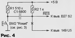
In Fig. 4 shows a diagram of a node allows you to choose games in cartridge, switchable by a signal reset.
The diagram in Fig. 5 shows how you can temporarily restore the functioning of the TRS with faulty node of the control voltage at the OS U2.1 (see Fig. 3).
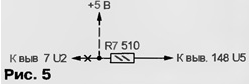
Circuit processor Board TRS, which should be broken by cutting the traces, in Fig. 4 and 5 are marked with crosses.
Common fault the video is bad soldering conclusions to VLSI the pads of the PCB. To search for such defects requires magnifying glass and fine needle gently, without much pressure, spend on all the findings of the GSI. Poorly soldered conclusion pretends to shake. To restore functionality enough soldering iron (free from excess solder!) to push the output to the pad and heat it for 1…2 C.
Literature
Author: S. Ryumik, Chernigov, Ukraine