


")

VCRs (videoplayer) company SHARP early issues with asymmetric the location of the slot often fail due to a malfunction elements of LSM. Defects, discussed below, most devices (such as VC-6V3, etc.) are manifested within two-three years depending on the intensity operation. This is caused, as shown, structural flaws CVL and non-compliance of the rules.
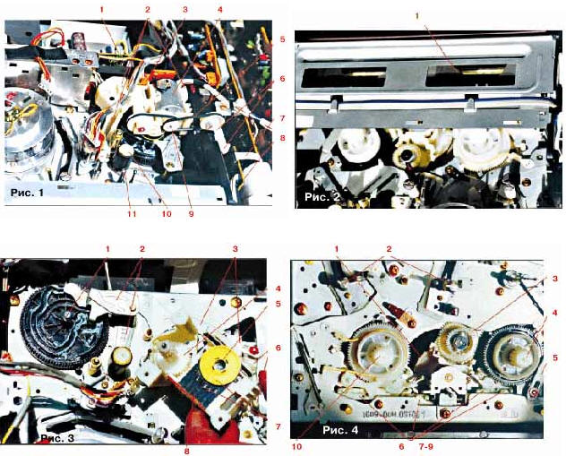
Appearance of nodes LSM video player, SHARP VC-6V3 from different angles is shown in Fig. 1-4. In the list of the most common faults is not specified cases, associated with defects themselves LSM and Rhu that affect the quality of the recording and play as they are quite detailed in technical literature, and they are common to all types of such devices. Here will be described the malfunction of the cassette, the program switch and strap node the intermediate gear.
1. The cassette is not charged, the engine fueling is not rotating
early check power source. To do this with a voltmeter measure (if possible) its output voltage at the connector (Fig. 1, POS. 1).
Then check the chip control engine fueling. It is easy to find - it installed perpendicular to the PCB and has 9 or 10 pins. Conclusions the power of the engine fueling is connected directly with its findings.
The control chip can be BA6209, BA6218, BA6219B or BA6418. Their the structural scheme shown in Fig. 5-8, respectively.
(click to enlarge)
Convinced of the receipt of the supply voltage on the chip from the source power. It is usually equal to 12 V. If the supply voltage on the pins no, check the serviceability of the elements included between the power source and circuit (for example, blocking capacitors and testing the resistors in Fig. 5).
It happens that the supply voltage to the control chip comes with the engine refills not included. Then check the engine itself (see Fig. 1, POS. 4). To disable this (if possible) connector that is connected to the node software mechanism (see Fig. 1, POS. 3), or otpaivaete power wires engine fueling. From an external power source serves voltage of 12 V at any polarity at the motor terminals. The rotation of the latter testifies to its health.
You should also verify the supply voltages on the findings MCU microcontroller unit (usually +5V). Next check the integrity of the conductors from the microcontroller to the chip of motor control stations (see Fig. 5-8).
Then control the accuracy of triggering mechanical sensor refills videotapes, an on-Board sensors of the cassette (see Fig. 1, POS. 8). In the initial state, the contacts must be closed. When inserting videotapes they open. In order to have access to the sensor, remove the front panel of the device (it is secured with plastic clips), disconnect flexible flat cable from the motherboard sensors (see Fig. 1, POS. 7), Unscrew the two screws fastening the cassette to the frame of LSM (often these screws are painted red paint) and remove the belt (see Fig. 1, POS. 5) with engine fueling. After this, slightly shaking, remove the cassette. When removing the cassette insert a videotape and press lightly on in the direction of motion, control the sensor refills cassettes.
If all of these actions have not resulted in Troubleshooting, the microcontroller of the device must be replaced.
Before returning to set the cassette in the recorder, note that box set was in an extreme forward position (see Fig. 2, POS. 1). If it got back, the rotation of the motor shaft filling (Fig. 1, POS. 6) shift it in forward position.
2. Do not run the command "Stop" and "Release the tape" out of position "Playback" or "Record"
When you run these commands LSM need to remove the tape from the drum and reverse (first one, then the other side) to rewind the tape for 1…2 each direction, and then unload the tape. Reversible rewinding a videotape perceived by the ear as two loud clicks at intervals of 2…3 seconds.
3. The tape is not rewound in one or both directions
4. The machine runs erratically: first, a team of management LSM executed, and after a while - not running
A common cause for these malfunctions (p. 2, 3, 4) can be Electromechanical skew LSM or malfunction of its elements. It is also possible malfunction of the microcontroller and the host management elements of LSM, but they will go discussed in the following articles.
In order to eliminate these defects, check the serviceability of the elements of LSM. First remove the front panel and the cassette (see claim 1). Then Unscrew the ring located on the perimeter of three screw attachment to LSM node engine fueling (see Fig. 1, POS. 2). Remember (mark) position strap software (see Fig. 3 and Fig. 4, POS. 6), the rocker arm (see Fig. 3, POS. 3; Fig. 4, POS. 5) and rocker arm pressure roller (see Fig. 3, POS. 2). Disconnect connector (see Fig. 1, POS. 3) and, slightly shaking the body node of engine fueling, remove it from side of LSM.
If the machine is in the Stop position, the control correctly align scratches program switch (see Fig. 3, POS. 7, 8). They should be one opposite to the other.
Then be convinced of serviceability of a software switch. To do this, remove with the disk (most often red, yellow or white, rice. 3, POS. 5), unclasping the latch anchorages in the inner hole. Check integrity pads and spring contacts, washed with alcohol and lubricate a small amount of petroleum jelly or special lubricant. Collect software switch.
Monitor the integrity of the deposited charge on the node engine fueling film resistors (in the model SHARP VC-6V3 they are marked as RB21-RB25).
Next remove the locking washer holding the rocker arm pressure roller (see Fig. 3, POS. 2) to remove the rocker. Remember (mark) position software gear and also take it off.
Bottom released two rocker: software strap (see Fig. 3, POS. 3) and strap the device for refilling the tape in Rhu (not shown). The teeth of both laths are fixed in grooves of the gear program. It is very important to remember (note) the position of the teeth in the grooves.
Check the integrity of the grooves of the gear program at both the top and bottom. Carefully remove the excess grease from the gears and handle it all surface grooves. To use a different grease for this purpose (for example, Litol) it is undesirable.
Also a small amount of grease removed handle fixing pins software gear (see Fig. 3, POS. 1) and expeditiously in the Moniteur gear (see Fig. 3, POS. 4).
If the gear is serviceable, set it in place, making sure that to teeth rocker strap software and devices tape refills in Rhu got into the corresponding grooves of the gear. Establish into place the rocker pressure roller and fixed lock washer. Manually reverse rotating software gear, check mechanical assemblies: motion software strap, change the height position of the intermediate gear (Fig. 4, POS. 3), the movement of the filling roller tape in Rhu forward and backward until it stops, movement pressure roller to the driving shaft (see Fig. 1, POS. 10, 11).
Pay special attention to software gear rotated without excessive effort. Maximum resistance to its rotation creates software strap, so at the moment of greatest resistance gear add grease in those nodes that interfere with the progressive movement of the strap (see Fig. 4, POS. 7-9). Reverse rotating gear software, "smear" lubricant software strap. The lubricant is removed from the node apparatus having the surplus, or acquire (it is called the lubricant of LSM for VCR).
Next, install in original position software gear, as shown in Fig. 3. Combine the risks of the program switch (light triangle opposite black) and set the node engine fueling in LSM so that the cut stem gear program coincided with the cut opening the program switch (see Fig. 3). Record the knot of engine fueling at LSM with three screws.
Then remove the main and idler gears (see Fig. 4, POS. 1 and 3 respectively), grease and install them into place. Pay special attention to ease of movement up-down intermediate gear without tulipani in extreme provisions. You should check the ease of rotation of podkastov (see Fig. 4, POS. 4 and 10), after releasing them from the brake pads.
After that, install the cassette into place and put his belt on the shaft engine fueling (see Fig. 1, POS. 5, 9, respectively). Tighten the screws mounting slot.
You have to keep the belts, suitable for the motor shaft refills, tight dressed and slipped on the pulleys. Sure good quality rubber belt, installed between the motor pinion and main gear (see Fig. 4, POS. 1). Re-check the build quality of the elements that connect the connector to the node engine fueling (see Fig. 1, POS. 3) and a loop (see Fig. 1, POS. 7) to the Board sensor cassette (see Fig. 1, POS. 8).
Finally include the apparatus and control the performance of LSM. If the fault persists, check more carefully the elements of LSM, the serviceability of photosensors movement of podkastov (located underneath) and cassette, as well as transistors that are on the Board of photosensors cassette. In the absence of defects replace a microcontroller.
The article says nothing about malfunctions of the engine drive shaft, but this - another time. Will give some maintenance tips LSM:
1. In LSM using a special grease mechanical parts, domestic analog on sale. If it is necessary to lubricate the elements, carefully remove the excess with other nodes.
2. The condition of the belts and Rhu is recommended to check at least once a year.
3. Cleaned drum and magnetic heads of the synchronization circuits and the sound follows thin lint-free muslin soaked in alcohol. Traffic Batista when cleaning must be along the direction of movement of magnetic tape with light pressure. Good replacement for alcohol may become a special fluid that is supplied with cleaning diskettes for personal computers.
4. No need to get involved in the adjustment of the internal brake podkastov. If them worn a felt strip, then it should be replaced. In the case of defective ("tight") videotapes pokatushki can not rotate. If they to increase the domestic slowdown (increase friction between the felt ring and the plastic rings of a braking device of polituchnica), there may be problems when working with damaged videotapes.
Author: A. Rodin, Moscow